Electric motor and rotor therefor

a technology of electric motors and rotors, which is applied in the direction of dynamo-electric machines, electric generators/motors, rotary current collectors, etc., can solve the problems of complex motion of winding machines and unfavorable heat dissipation

Active Publication Date: 2010-01-21
JOHNSON ELECTRIC SA
View PDF4 Cites 17 Cited by
  • Summary
  • Abstract
  • Description
  • Claims
  • Application Information

AI Technical Summary

Problems solved by technology

In the winding arrangement shown in FIG. 6, the motion of the winding machine is complex and requires winding of the winding coils and winding of the equalizers.
Moreover, because the equalizer lines 61-65 are required to pass full armature current, they are required to be as thick as the winding coil, and because the equalizer lines are directly connected from one commutator bar hook to another commutator bar hook they are accumulated on the neck of the commutator between the bars and the rotor core and are not beneficial to heat dissipation.

Method used


Image

  • Electric motor and rotor therefor
  • Electric motor and rotor therefor
  • Electric motor and rotor therefor

Examples


Embodiment Construction

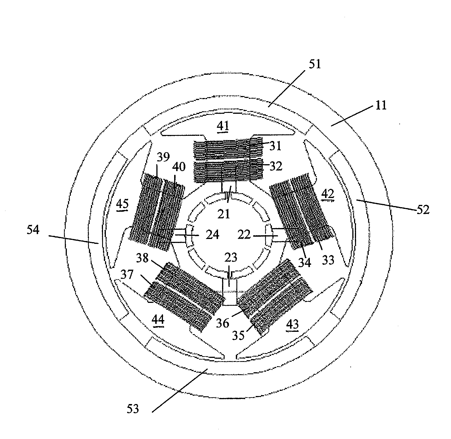
[0023]FIG. 1 illustrates a PMDC motor (permanent magnet direct current motor) according to a first, preferred embodiment of the present invention. The motor has a stator, brush gear and a rotor. The stator comprises a housing or yoke 11, and four permanent magnets 51-54 fitted to an inner surface of the yoke. The brush gear has four brushes 21-24 arranged to make sliding contact with a brush contact surface of the commutator for transferring electrical power to the rotor.

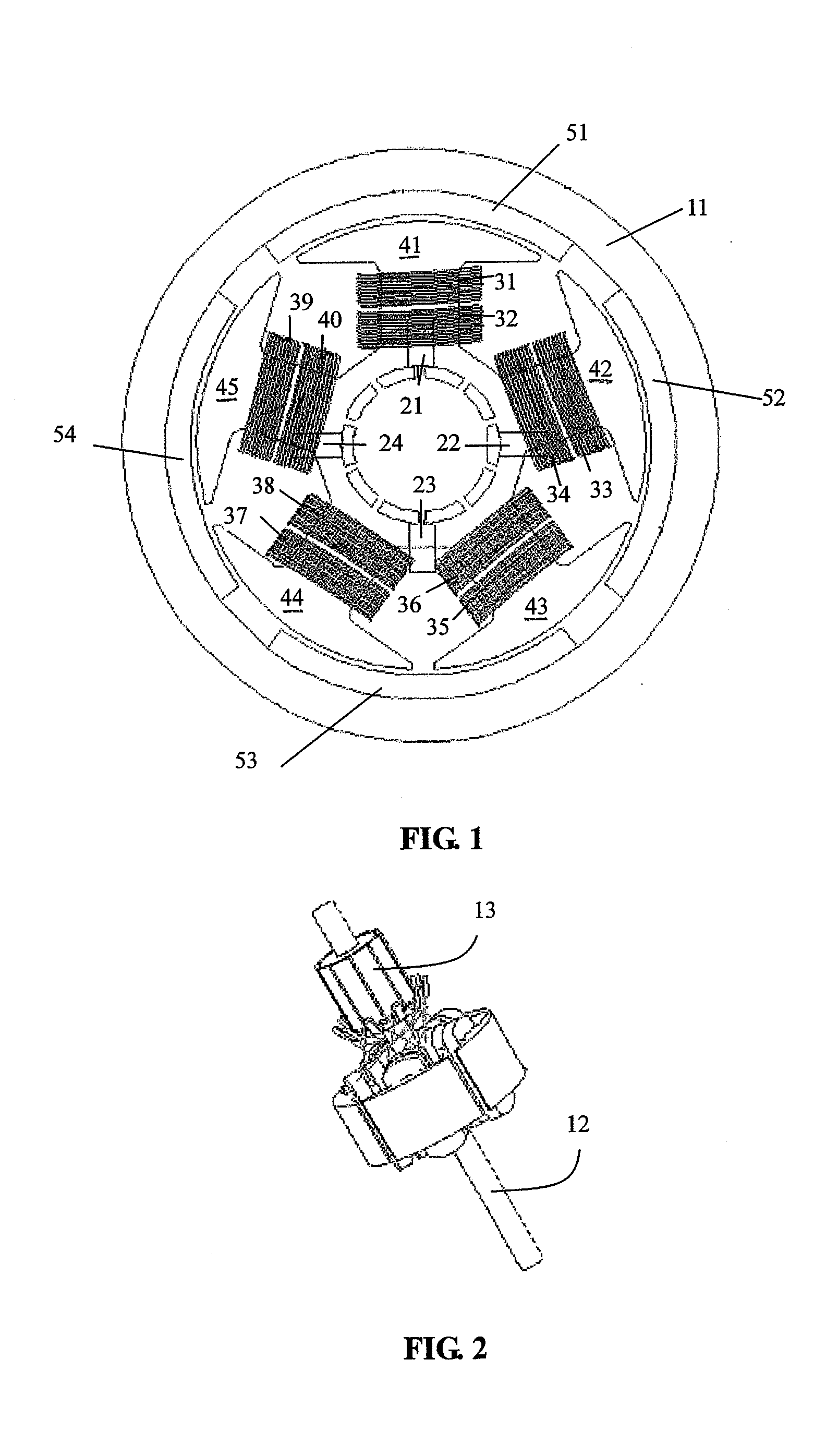
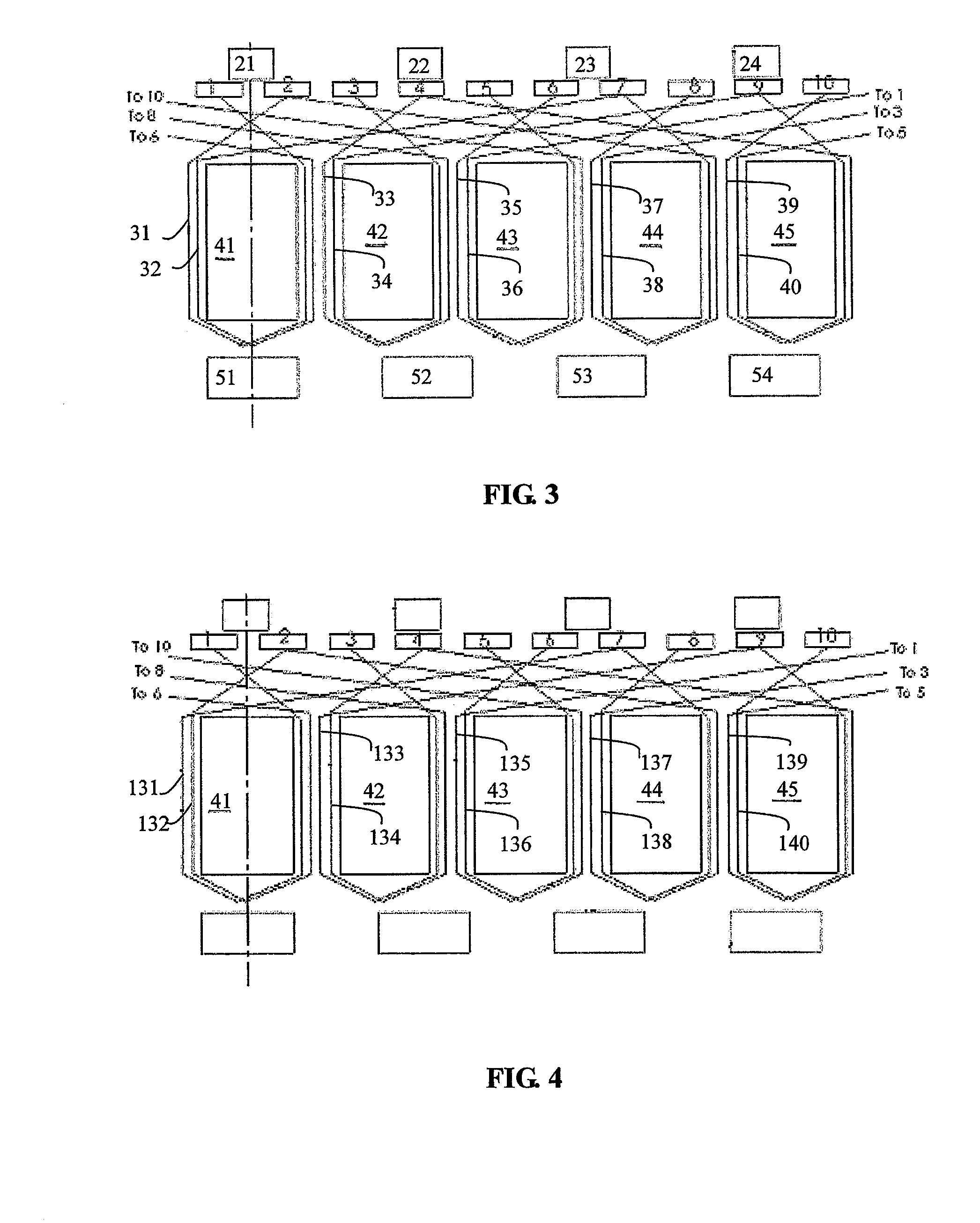
[0024]FIG. 2 illustrates the rotor of FIG. 1. The rotor comprises a shaft 12, a rotor core mounted on the shaft 12, and a commutator 13 fitted to the shaft 12 next to the rotor core. The rotor core comprises five teeth 41-45 extending towards and facing the permanent magnets 51-54 across a small air gap. The commutator 13 has ten bars 1-10 arranged to form the brush contact surface. Each tooth 41-45 is wound with two windings 31-40 and the windings are terminated or otherwise electrically connected to termination ho...


PUM


Abstract

An electric motor comprises: a rotor; a stator; and brush gear. The rotor has a shaft, a rotor core and a commutator fitted to the shaft. The rotor core has 5n teeth, n being a positive integer. Two coils are wound in each tooth with each coil being wound about a single tooth and having two ends. The commutator has 10n bars forming a brush contact surface. The stator comprises a yoke and a plurality of permanent magnets installed at an inner surface of the yoke and facing the rotor core. The brush gear has a plurality of carbon brushes arranged to make sliding contact with the brush contact surface of the commutator. The ends of the two coils wound in each tooth are respectively connected to two pairs of adjacent bars and the center line between one pair of the two pairs of adjacent bars and the center line between the other pair of the two pairs of adjacent bars are diametrically opposed.

Description

CROSS REFERENCE TO RELATED APPLICATIONS[0001]This non-provisional patent application claims priority under 35 U.S.C. §119(a) from Patent Application No. 200810068577.0 filed in The People's Republic of China on Jul. 21, 2008.FIELD OF THE INVENTION[0002]This invention relates to an electric motor and in particular, to a rotor for a PMDC motor.BACKGROUND OF THE INVENTION[0003]Generally, the number of commutator bars (referred to as bar number), the number of rotor poles or slots (referred to a slot number) and the number of winding coils of a permanent magnet DC motor are the same. A standard commutator only sustains roughly stable commutation voltage. Even so, commutation sparks are visably generated between adjacent commutator bars as the brush pass over them. To improve commutation, sometimes the commutator bar number, the number of winding coils is twice the rotor slot number. A known micromotor adopts four poles (stator poles) and five slots, because it has the advantages of simp...

Claims


Application Information

Patent Timeline
Patent Type & Authority Applications(United States)
IPC IPC(8): H02K23/38H02K23/04H02K23/26
CPCH02K23/38H02K23/30
Inventor ZHAO, JIANLI, YONGJIN, CHANG LIN
Owner JOHNSON ELECTRIC SA
Why Eureka
Try Eureka