Methods and apparatus for power supply load dump compensation

Active Publication Date: 2010-01-21
INFINEON TECH AUSTRIA AG
View PDF32 Cites 144 Cited by
  • Summary
  • Abstract
  • Description
  • Claims
  • Application Information

AI Technical Summary

Problems solved by technology

For today's highest current applications, the active components are typically discrete due to the difficulty in thermal and electrical design of a fully integrated stage.

Method used


Image

  • Methods and apparatus for power supply load dump compensation
  • Methods and apparatus for power supply load dump compensation
  • Methods and apparatus for power supply load dump compensation

Examples


Embodiment Construction

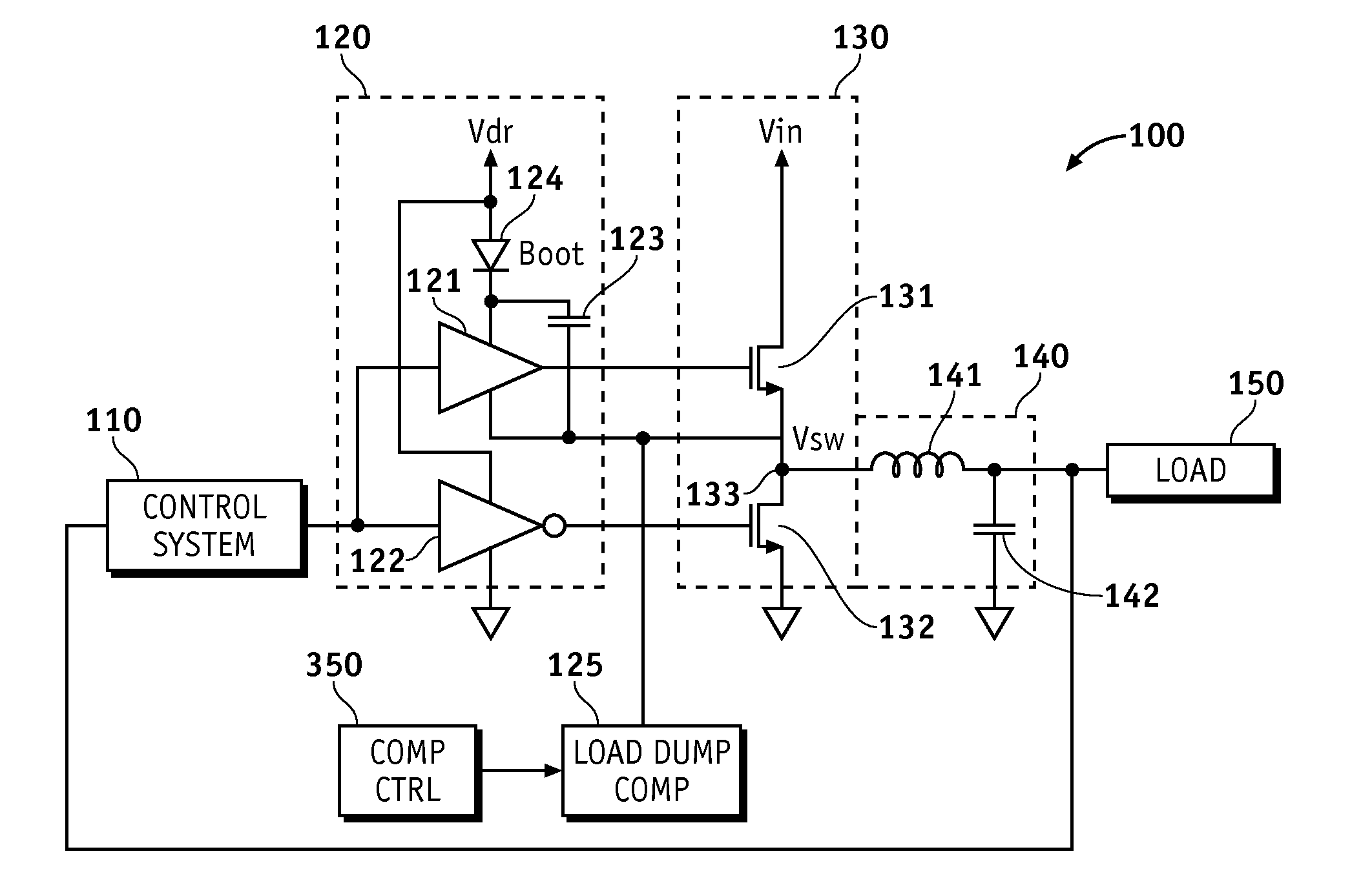
[0013]Various aspects of the present invention may be described in terms of functional block components and various processing steps. Such functional blocks and steps may be realized by any number of hardware or software components configured to perform the specified functions and achieve the various results. For example, systems and methods according to various aspects of the present invention may employ integrated components and electronic devices that may be implemented in any appropriate manner, such as integrated circuits, logic arrays, processors, transistors, resistors, capacitors, inductors, and the like. In addition, various aspects of the present invention may be practiced in conjunction with any suitable converter and / or regulator applications, and the systems described are merely exemplary applications for the invention. Further, various aspects of the present invention may employ any number of conventional techniques for regulating power, modifying a waveform, driving a...


PUM


Abstract

Methods and apparatus for power supply load dump compensation according to various aspects of the present invention may operate in conjunction with a power stage system, such as a power stage system comprising a bootstrapped driver circuit and a power stage responsive to the driver circuit. The power stage system may further include a load dump compensation circuit connected to the driver circuit, wherein the load dump compensation circuit is configured to remove a bias current generated by the bootstrapped driver circuit. Various aspects of the present invention may be implemented in conjunction with any appropriate power supply, such as a switching regulator, for example a buck converter.

Description

CROSS-REFERENCES TO RELATED APPLICATIONS[0001]The present application claims the benefit of U.S. Provisional Patent Application Ser. No. 61 / 082,049, filed Jul. 18, 2008, entitled “Methods and Apparatus for Load Dump Compensation of Bootstrapped Gate Driver Bias Current in Switching Regulators”, and U.S. Provisional Patent Application Ser. No. 61 / 082,043, filed Jul. 18, 2008, entitled “Methods and Apparatus for Load Dump Compensation of Bootstrapped Gate Driver Bias Current in Switching Regulators”, and incorporates these applications by reference.BACKGROUND OF THE INVENTION[0002]Switching power supplies are popular for high power applications because of their high efficiency and the small amount of area / volume they require. Popular switching supply topologies include buck, boost, buck-boost, forward, flyback, half-bridge, full-bridge, and SEPIC topologies. Buck converters are particularly well suited for providing the high current at low voltages needed by today's high performance i...

Claims


Application Information

Patent Timeline
Patent Type & Authority Applications(United States)
IPC IPC(8): G05F1/10
CPCH02M3/156H03K7/08H02M2001/0019H02M1/0019Y10S323/901
Inventor TANG, BENJAMIMNG, TIMOTHY M.
Owner INFINEON TECH AUSTRIA AG
Why Eureka
Try Eureka