Bi-directional print masking

a printing masking and bi-directional technology, applied in the field of inkjet printing systems, can solve the problems of significant differences in the characteristics prone to banding artifacts, and undesirable grainy or noisy appearance of the reproduced image, so as to and reduce the bi-directional banding artifa

Active Publication Date: 2010-01-21
EASTMAN KODAK CO
View PDF23 Cites 32 Cited by
  • Summary
  • Abstract
  • Description
  • Claims
  • Application Information

AI Technical Summary

Benefits of technology

[0027]It is an advantage of the present invention that images with reduced bidirectional banding artifacts can be produced for inkjet printers using bi-directional multi-pass print modes.
[0028]It has the additional advantage that it will reduce bidirectional banding artifacts that result from both differences in the order of ink laydown, as well as the timing between ink laydown on different passes.
[0029]It is yet another advantage of the present invention that the reduction in bidirectional banding artifacts can be achieved without a significant impact on the printing speed. In some embodiments of the present invention, the impact on the printing speed will be negligible.

Problems solved by technology

This can give the reproduced image an undesirable grainy or noisy appearance often referred to as “coalescence”.
A common problem with inkjet printers that utilize bi-directional multi-pass printing is that they can be susceptible to banding artifacts caused by differences in the order of ink laydown and the timing between ink laydown on different passes.
The differences in the time delays, both across the page and from swath-to-swath, can result in significant differences in the characteristics of the reproduced image.
This can result in noticeable differences in the density of the printed region.
Additionally, there can also be noticeable differences in the image structure characteristics.
Typically, the swath-to-swath differences at a given horizontal position in the image are much more objectionable than the variations across the page.
For many combinations of ink, media and print mode, the bi-directional banding artifacts have been found to be quite objectionable.
Bi-directional banding artifacts can be even more severe for the case of printing color images with multiple color inks.
This can cause objectionable periodic bi-directional banding artifacts that vary in both color (lightness, hue and / or chroma) and image structure.
The magnitude of the bi-directional banding artifacts is often much more objectionable for image regions printed with two or more colored inks than it is for image regions using only a single ink since the reproduced color can be strongly influenced by which ink drops are printed on top.
However, this solution significantly limits the throughput of the printer since it is necessary to wait for the printhead to return back to the starting position before printing another swath.
Another step that can be taken is to slow down the printing speed to give the ink / media interactions more time to stabilize between passes, but this too will significantly impact the printer throughput.
Note that while this approach can help reduce the contributions of the bi-directional banding that are due to differences in the timing between ink laydowns, it will not alleviate the contributions that result from differences in ink ordering.
However, this will also have a direct impact on the throughput of the printer, so it is not a desirable solution for applications where print speed is a critical requirement.
However, they will be ineffective at compensating for the contributions of the bidirectional banding that result from differences in the timing between ink laydowns since these effects will vary from left to right across the page, and these methods do not provide for changing the ink laydown as a function of the horizontal position.

Method used


Image

  • Bi-directional print masking
  • Bi-directional print masking
  • Bi-directional print masking

Examples


Embodiment Construction

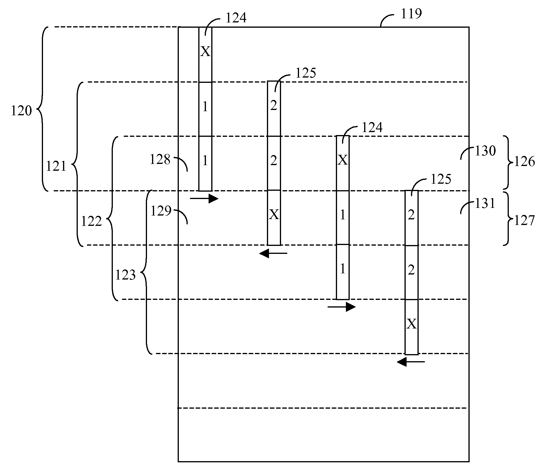
[0041]The present invention represents a method to reduce bi-directional banding artifacts typically associated with bi-directional multi-pass printing on an inkjet printer by way of a novel method for defining different print masks for leftward and rightward printing passes. The leftward and rightward print masks are defined such that the order of ink laydown and the timing between ink laydown on different passes are substantially constant for a given horizontal position within the image, independent of the vertical position within the image.

[0042]Turning now to FIG. 6, the method of the present invention will be described. A page 119 is printed on an inkjet printer using a bi-directional multi-pass print mode by moving a printhead horizontally across the page in a first direction (e.g. rightward), firing ink drops from nozzles on the printhead as it passes over a receiver media such as paper. The paper is then advanced by some distance less than the height of the printhead, and th...


PUM


Abstract

A method for reducing banding artifacts for bi-directional multi-pass printing on an inkjet printer utilizing a printhead with a plurality of ink nozzles includes defining different print masks to be used for leftward and rightward printing passes such that both the order of ink laydown and the timing between ink laydown on different passes are each substantially constant for a given horizontal position within the image, independent of the vertical position within the image; and printing an input image on the inkjet printer with the defined print masks using a bi-directional multi-pass print mode.

Description

FIELD OF THE INVENTION[0001]This invention pertains to the field of inkjet printing systems, and more particularly to a method for reducing banding artifacts associated with bi-directional multi-pass printing on an inkjet printer.BACKGROUND OF THE INVENTION[0002]A typical inkjet printer reproduces an image by ejecting small drops of ink from a printhead containing ink nozzles, where the ink drops land on a receiver medium (typically paper) to form ink dots. Inkjet printers typically reproduce color images by using a set of color inks, usually cyan, magenta, yellow, and black. It is well known in the field of inkjet printing that if ink drops placed at neighboring locations on the page are printed at the same time, then the ink drops tend to flow together on the surface of the page before they soak into the page. This can give the reproduced image an undesirable grainy or noisy appearance often referred to as “coalescence”. It is known that the amount of coalescence present in the pr...

Claims


Application Information

Patent Timeline
Patent Type & Authority Applications(United States)
IPC IPC(8): B41J29/38
CPCG06K15/107B41J19/142
Inventor SPAULDING, KEVIN E.COUWENHOVEN, DOUGLAS W.REEM, RICHARD C.RUEBY, CHRISTOPHER
Owner EASTMAN KODAK CO
Why Eureka
Try Eureka