

Display
a technology of display and control film, applied in the field of display, can solve the problems of reducing the efficiency of light utilisation, light propagation, and relatively inefficient type of light control film
- Summary
- Abstract
- Description
- Claims
- Application Information
AI Technical Summary
Benefits of technology
Problems solved by technology
Method used
Image

Examples
embodiment 1
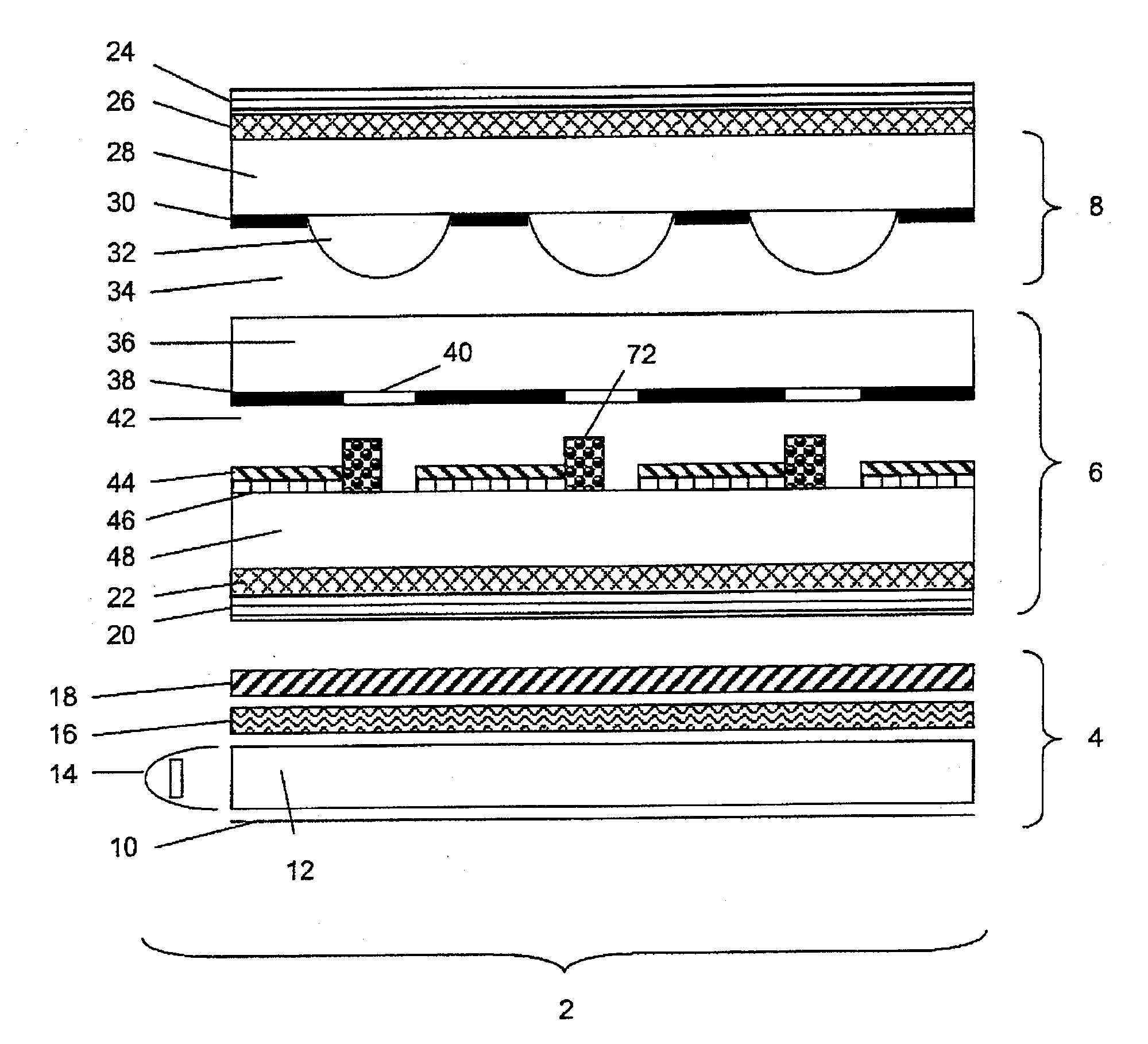
[0086]A cross-section of display according to a first embodiment of the invention is shown in FIG. 2. According to the invention, a parallax optic, 8, in this example comprising a series of microlenses, 32, is placed in registration with the pixels of a pixellated display panel. The display panel may be a liquid crystal panel comprising a liquid crystal display panel with a backlight behind, in which case the pixels may be represented by the colour filters, 40, or it may comprise an emissive display panel such as an organic light emitting display, or it may comprise any other type of display panel which is made up of a number of pixels. The parallax optic is spaced a defined distance from the front of the display panel by a medium, 34, which may be air or a material with a lower refractive index than the material from which the microlenses are made, and each lens is registered with one pixel aperture such that light is imaged substantially in a direction normal to the panel, 66, wit...
embodiment 2 (preferred embodiment)
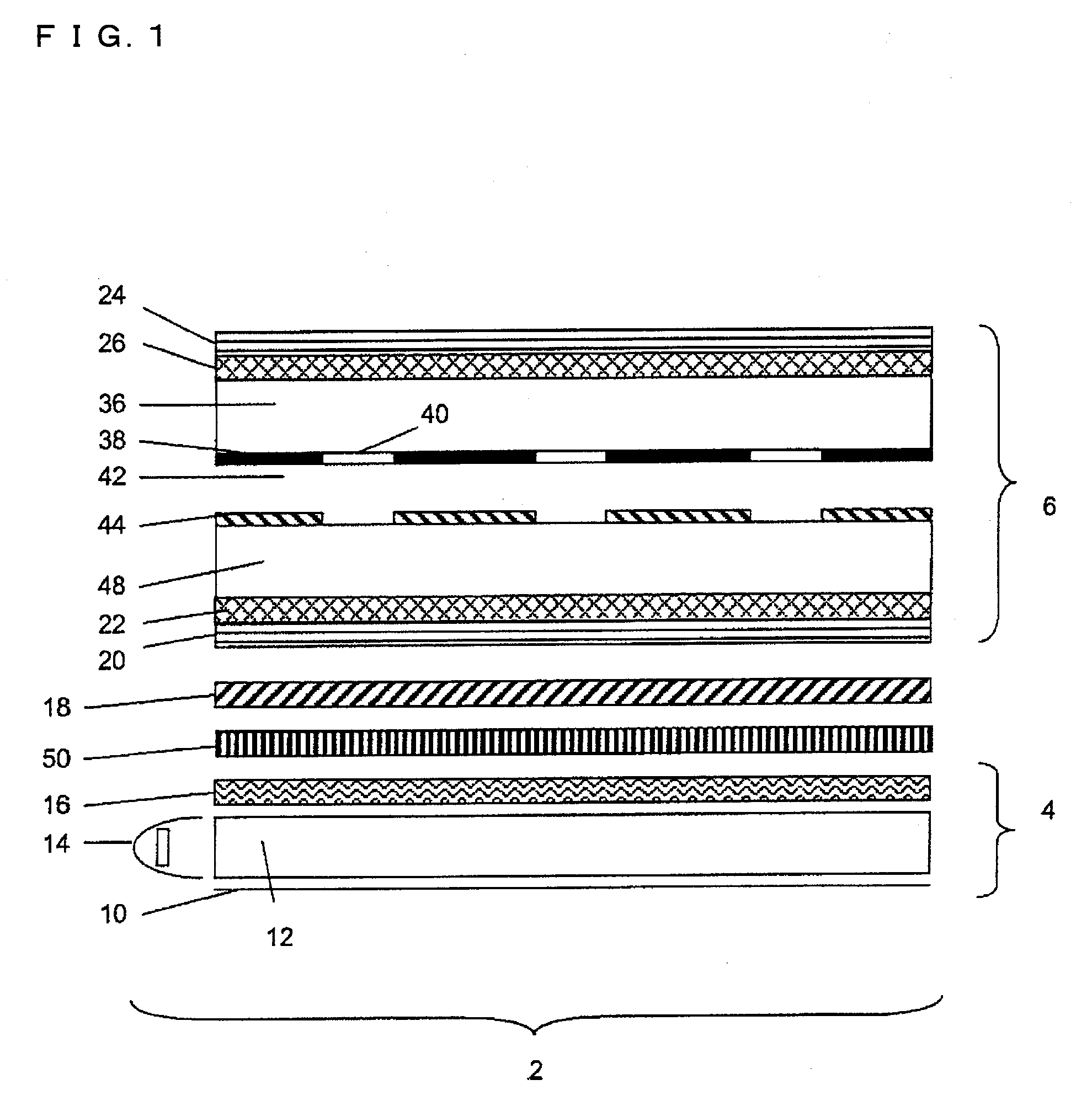
[0102]FIG. 4 illustrates a display of an embodiment of the invention, comprising a parallax optic, in this embodiment a microlens array 8, and an image display panel 6. The image display panel is a pixellated image display panel. The parallax optic is arranged such that an element of the parallax optic images no more than one pixel of the display panel or no more than one row / column of pixels of the display panel. In general each element of the parallax optic images one pixel of the display panel or one row / column of pixels of the display panel although, as described with reference to FIG. 19 below, it is possible for two or more elements of the parallax optic to be associated with a pixel (or row / column of pixels) so that an element of the parallax optic images only part of a pixel (or part of a row / column of pixels). FIG. 4 illustrates an embodiment for use in one of the aforementioned applications, in which the parallax optic, 8, is precisely registered such that the apexes of th...
embodiment 3
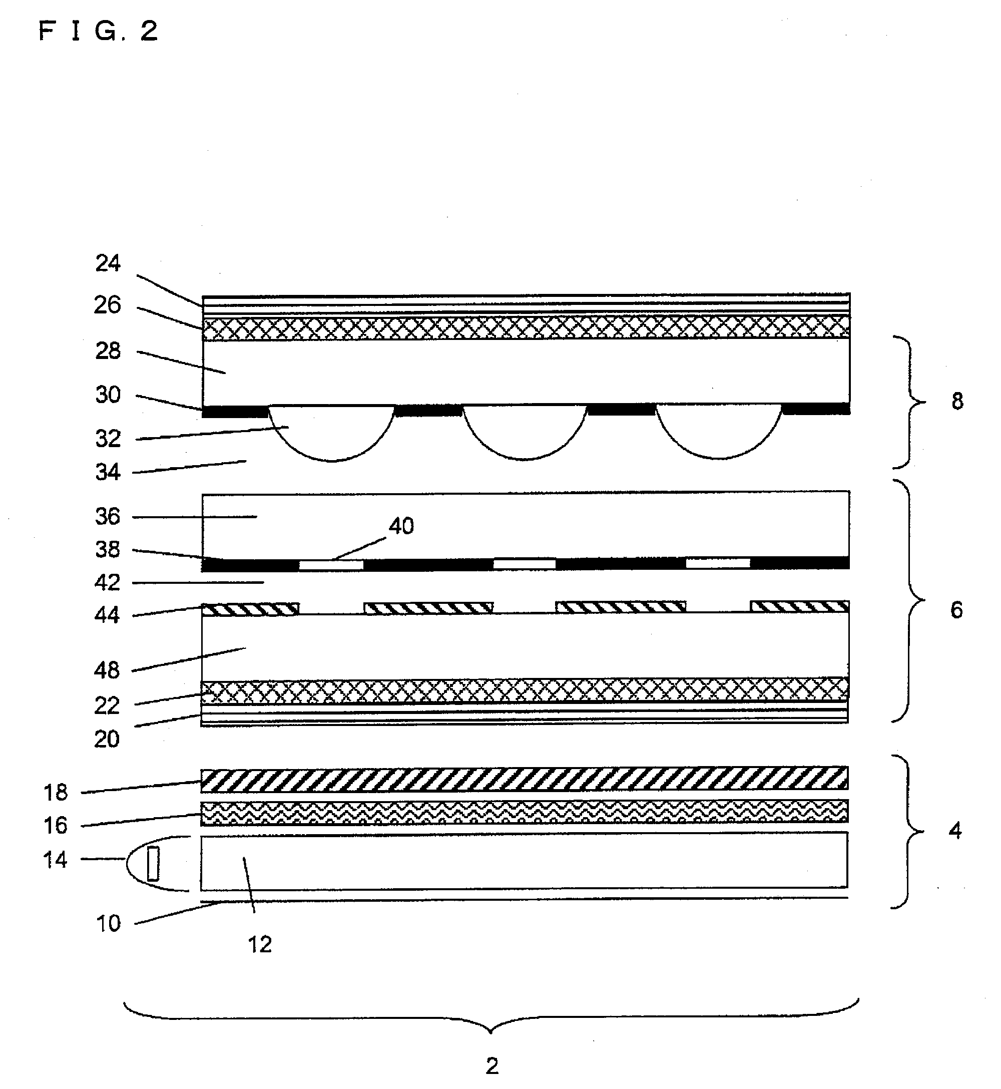
[0105]In certain situations it is desirable to have the viewing window such that the bisectrix of the angular range of the viewing window is not normal to the display. This is illustrated in FIG. 8, in which the display 2 is tilted in such a way that the viewing window would in part be reflected off the windscreen, 62, of the car and back to the viewer, 56 if the bisectrix is normal to the display face. It is possible to offset the microlens array with respect to the pixel apertures, parallel to the plane of the display, such that the apex of the lens is no longer centred on the pixel aperture, as shown in FIG. 7. Apart from this offset of the microlens array with respect to the pixel apertures, the display of FIG. 7 corresponds generally to the embodiment of FIG. 4 and the parallax optic 8 (in this case a microlens array) again restricts the angular spread of light emitted from the display. Offsetting the microlens array like this will cause the pixel apertures to be imaged in a di...
PUM
 Abstract
Description
Claims
Application Information