Method of mapping OPUke into OTN frames

a mapping method and technology of opukes, applied in the field of mapping opukes into otn frames, can solve problems such as system failur

Inactive Publication Date: 2010-01-21
ALTERA CANADA
View PDF3 Cites 15 Cited by
  • Summary
  • Abstract
  • Description
  • Claims
  • Application Information

AI Technical Summary

Problems solved by technology

However, because the 10 GbE LAN PHY has a ±100 ppm capability, if the signal was wrapped during multiplexing, the ±100

Method used


Image

  • Method of mapping OPUke into OTN frames
  • Method of mapping OPUke into OTN frames
  • Method of mapping OPUke into OTN frames

Examples


Embodiment Construction

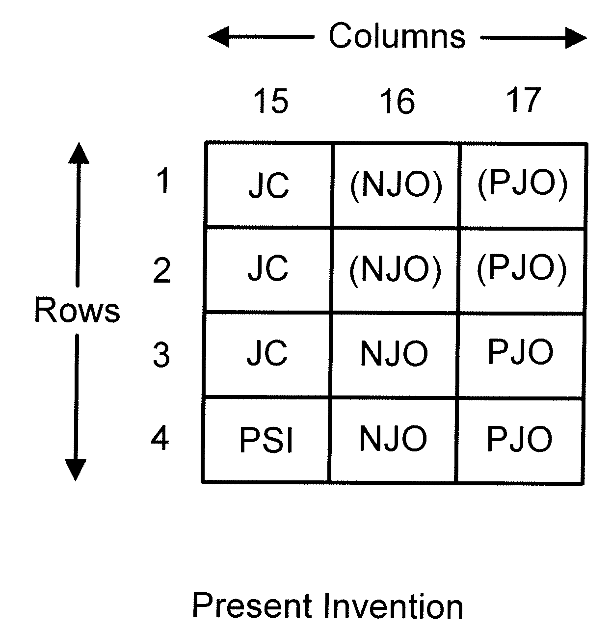
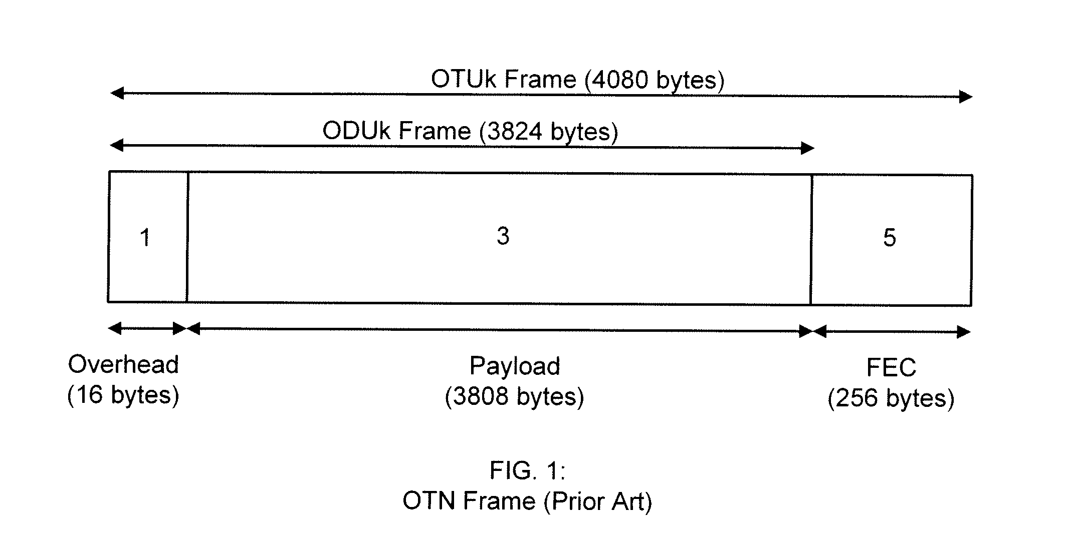
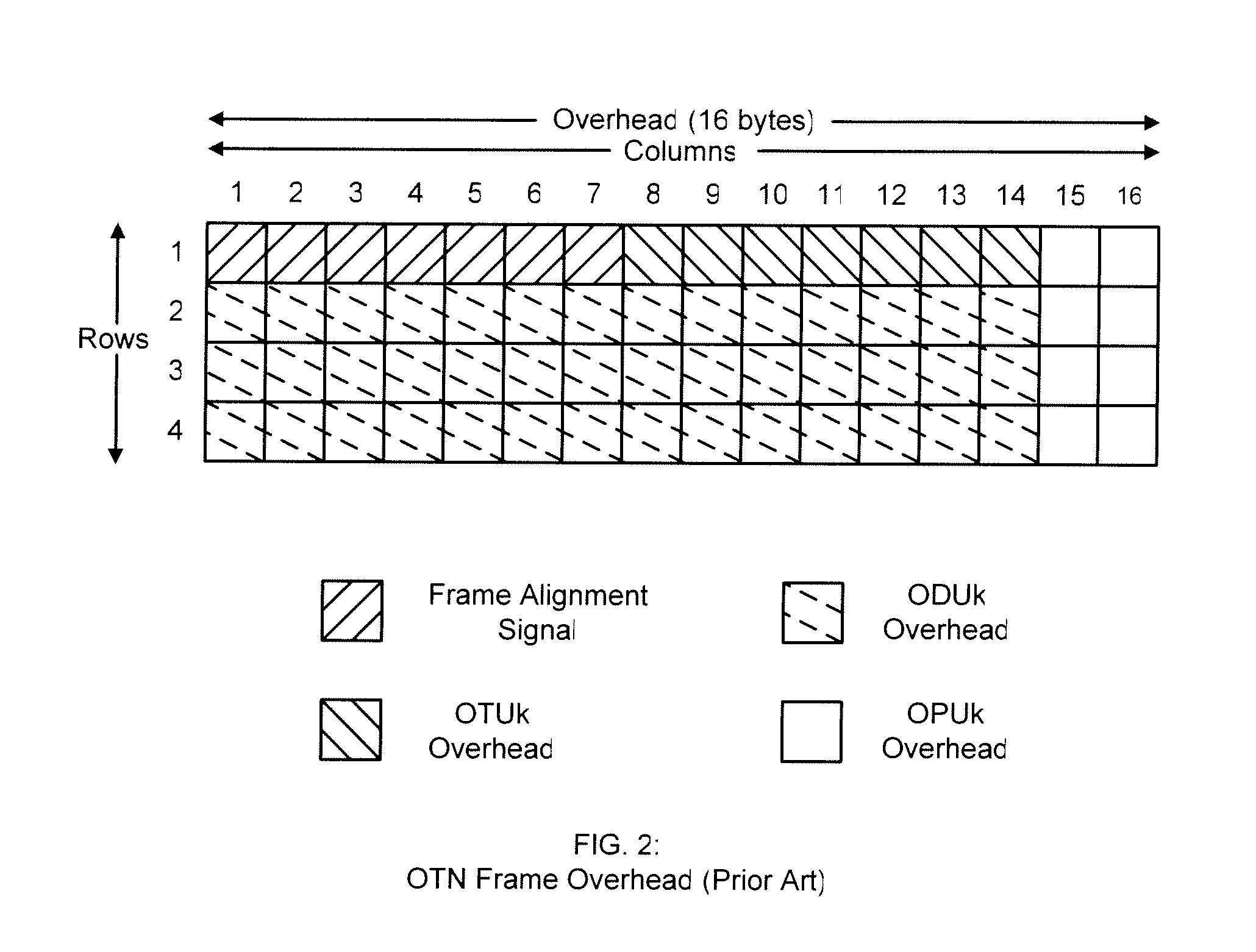
[0026]The present invention discloses a method of mapping Optical Payload Unit (OPU) k (k=1, 2, 3 or any positive integer) Ethernet signals (E) into Optical Transport Network (OTN) frames while increasing the Constant Bit Rate (CBR) for 10 Gigabit Ethernet (10 GbE) Local Area Network Physical Layer (LAN PHY). As specified by ITU-T G.709, the OPUk Overhead (OH) includes: bytes reserved for future international standardization (RES) in rows 1-3, column 15; the Payload Structure Identifier (PSI), located in row 4, column 15; Justification Control (JC) bytes in rows 1-3, column 16; the Negative Justification Opportunity (NJO) byte in row 4, column 16; and the Positive Justification Opportunity in row 4, column 17.

[0027]In an illustrative embodiment of the present invention, such Justification OH (JOH) bytes are relocated within the OPUk frame. As disclosed in FIG. 6, the present invention relocates the three JC bytes from their standardized locations in rows 1-3, column 16, into the RES...


PUM


Abstract

The present invention discloses a method of mapping Optical Payload Unit (OPU) k (k=1, 2, 3 or any positive integer) Ethernet signals (E) into Optical Transport Network (OTN) frames for 10 Gigabit Ethernet (10 GbE) Local Area Network Physical Layer (LAN PHY), wherein OPUk Overhead (OH) is altered by the relocation of Justification Control (JC) bytes, from the standardized ITU-T G.709 locations, into the novel locations of rows 1-3 of column 15. This allows for rows 1-4 of column 16 to be available for any type of Justification Overhead (JOH), such as four Negative Justification Opportunity (NJO) byte locations. Four NJO byte locations, combined with four Positive Justification Opportunity (PJO) byte locations in rows 1-4 of column 17, provides for up to nine justification state choices to be determined by the JC bytes. In addition, the ability to add or remove a plurality of two, three or fours bytes from OTN Payload can double, triple, or quadruple the standardized maximum bit rate tolerance of ±65 parts per million (ppm).

Description

CROSS-REFERENCE TO RELATED APPLICATIONS[0001]Not ApplicableSTATEMENT REGARDING FEDERALLY SPONSORED RESEARCH OR DEVELOPMENT[0002]Not ApplicableREFERENCE TO SEQUENCE LISTING, A TABLE, OR A COMPUTER PROGRAM LISTING COMPACT DISC APPENDIX[0003]Not ApplicableBACKGROUND OF THE INVENTION[0004]1. Technical Field of the Invention[0005]The present invention relates to the mapping of OPUke into OTN frames for 10 GbE LAN PHY.[0006]2. Background of the Invention[0007]The International Telecommunication Union, Telecommunication Standardization Sector (ITU-T) Recommendation G.709, “Interfaces for the optical transport network (OTN),” defines the Optical Transport Network (OTN) frame as consisting of three main sections; the 16 byte overhead (OH) section; the 3808 byte payload (PL) section; and the 256 byte forward error correction (FEC) section (FIG. 1). OTN is able to transport via three standard rates, Optical Data Unit (ODU) k, where k=1, 2 or 3.[0008]The 16 byte OH section is comprised of the O...

Claims


Application Information

Patent Timeline
IPC IPC(8): H04J14/00
CPCH04J3/07H04J2203/0085H04J3/1658
Inventor HAAS, WALLY
Owner ALTERA CANADA
Why Eureka
Try Eureka