Fuel cell

a fuel cell and cell technology, applied in the field of fuel cells, can solve the problems of insufficient thermal shock resistance, difficult to distribute reactant gas uniformly in the layer, and insufficient generation of power in the region, and achieve the effect of efficiently extracting generated power

Inactive Publication Date: 2010-01-21
NISSAN MOTOR CO LTD
View PDF11 Cites 16 Cited by
  • Summary
  • Abstract
  • Description
  • Claims
  • Application Information

AI Technical Summary

Benefits of technology

[0005]In this fuel cell, the current collector is disposed between the mutually adjacent solid electrolyte fue...

Problems solved by technology

However, in a layer where the current collector is located between the solid electrolyte fuel cell units, it is difficult to distribute the reactant gas uniformly in that layer.
Accordingly, there is a risk tha...

Method used


Image

  • Fuel cell
  • Fuel cell
  • Fuel cell

Examples


first embodiment

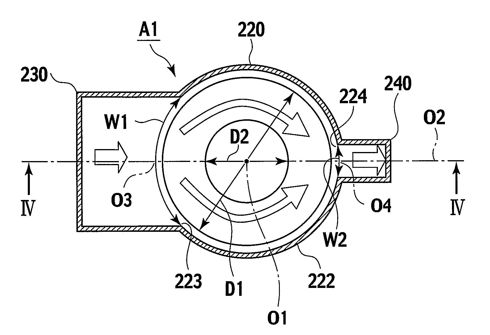
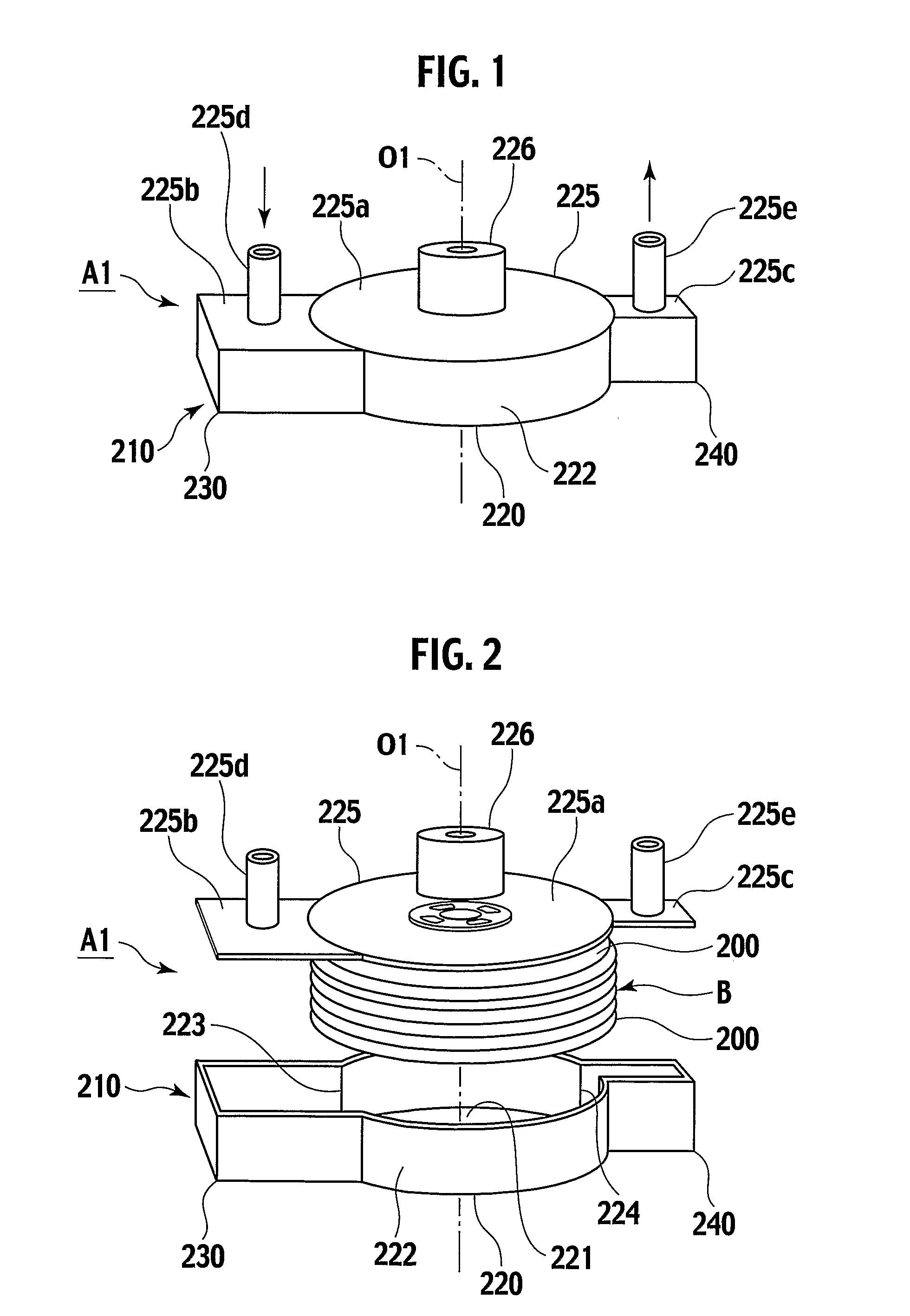
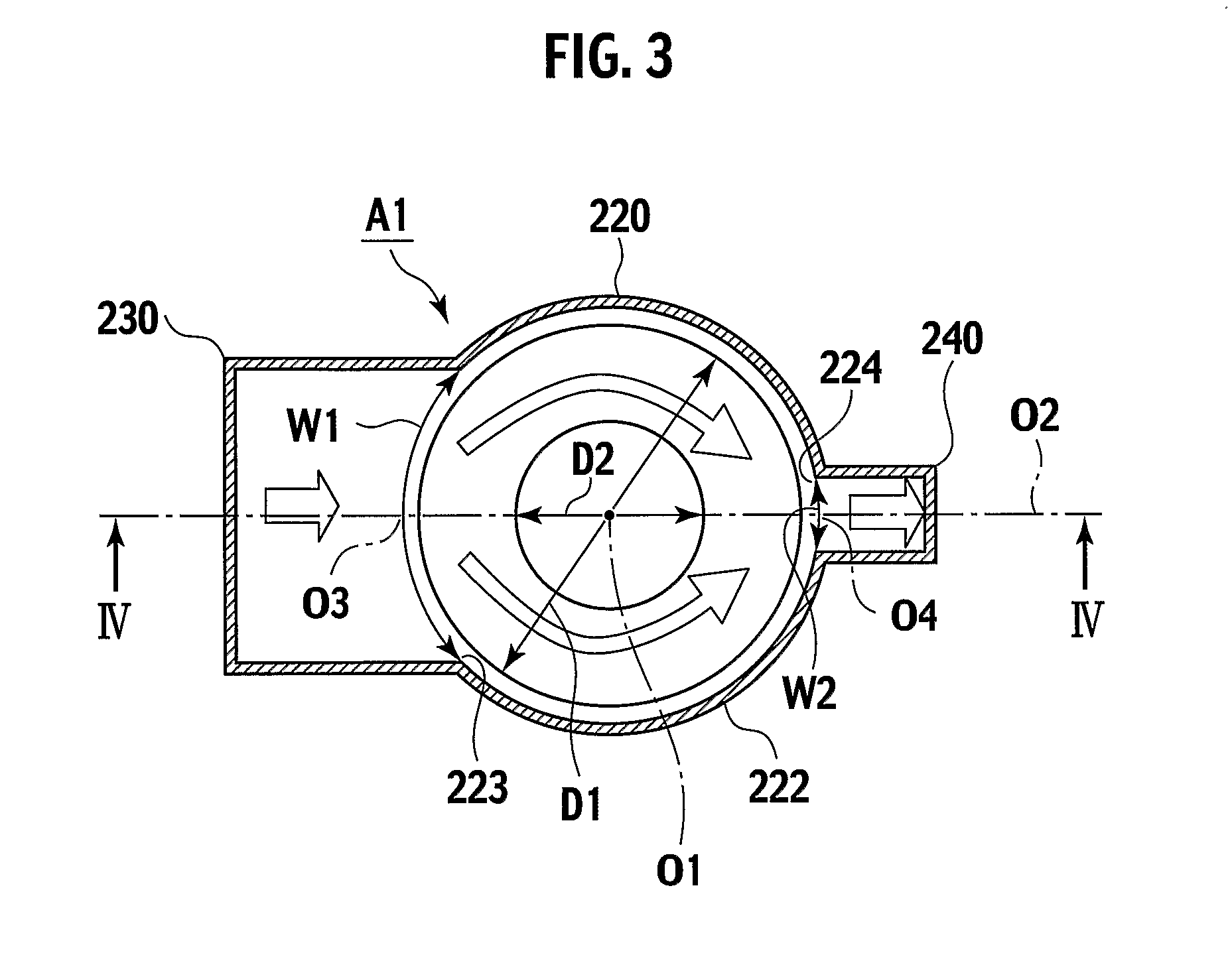
[0047]A fuel cell A1 according to a first embodiment of the present invention will be described in detail with reference to FIG. 1 to FIG. 5.

[0048]The fuel cell A1 includes a stack-structured member B and a casing 210 for housing the stack-structured member (hereinafter simply referred to as a “cell stack”) B. Two kinds of reactant gases flow separately from each other inside the cell stack B and inside the casing 210. The fuel cell A1 generates power by receiving the supply of these reactant gases.

[0049]The cell stack B includes multiple solid electrolyte fuel cell units 200 which are stacked in a stacking direction while providing inter-unit spaces S between the respective units.

[0050]Here, the expression “to stack” means to stack the multiple solid electrolyte fuel cell units (hereinafter simply referred to as “cell units”) 200 while providing the inter-unit spaces S between the respective units.

[0051]The “inter-unit spaceS” is provided to have one reactant gas out of the two kin...

second embodiment

[0082]Next, a fuel cell A2 according to a second embodiment of the present invention will be described with reference to FIG. 6 to FIG. 9.

[0083]The fuel cell A2 includes a cell stack 11 and a casing 10 for housing the cell stack 11. The casing 10 includes a casing body 12 that surrounds the cell stack 11, and a gas introduction portion 12A and a gas discharge portion 12B which are provided in a protruding manner on mutually opposite side surfaces of the casing body 12.

[0084]The casing body 12 includes: a bottom plate 12c having a circular shape in a plan view, and covering one end side (a lower end side) in the stacking direction of the cell stack 11; a peripheral wall 12d extending upward in the stacking direction from a peripheral portion of the bottom plate 12c along a side surface of the cell stack 11, and surrounding the side surface of the cell stack 11; and a lid member (an upper plate) 12e being welded over the entire periphery onto an upper end edge of the peripheral wall 1...

third embodiment

[0133]FIG. 12 to FIG. 14 show a fuel cell according to a third embodiment of the present invention.

[0134]A fuel cell A3 according to this embodiment has a configuration to provide a casing body 72 (a plate thickness of 0.5 mm) made of stainless steel (SUS310, JIS) with two gas inlet openings 72a and one gas outlet opening 72b. The total opening width dimension W1 of the two gas inlet openings 72a is set greater than the total opening width dimension W2 of the gas outlet opening 72b.

[0135]Two gas introduction portions 72A and one gas discharge portion 72B are provided in a protruding manner beside the casing body 72. Configurations of the respective gas introduction portions 72A and the gas discharge portion 72B are similar to those in the above-described embodiments.

[0136]In this embodiment, a gas flow-regulating member is formed of a ceramic sheet 77 attached to an inner side surface of a metal corrugated plate 76. As shown in FIG. 13, the metal corrugated plate 76 has a plate thi...


PUM


Abstract

A fuel cell (A1) includes a cell stack (B) and a casing (210) for housing the cell stack (B), and is supplied with two reactant gases flowing separately from each other. The cell stack (B) includes a plurality of solid electrolyte fuel cell units (200) stacked on one another with inter-unit spaces provided therebetween. One of the reactant gases is supplied to the inter-unit spaces and used for power generation. The casing (210) includes a peripheral wall (222) surrounding the cell stack (B). The peripheral wall (222) is provided with at least one gas inlet opening (223) for introducing the one of the reactant gases into the inter-unit spaces and at least one gas outlet opening (224) for discharging the introduced reactant gas, wherein total opening width dimension of the gas inlet opening (223) is greater than total opening width dimension of the gas outlet opening (224).

Description

TECHNICAL FIELD[0001]The present invention relates to a fuel cell including a casing that houses a stack-structured member having multiple solid electrolyte fuel cell units stacked therein.BACKGROUND ART[0002]U.S. Pat. No. 6,344,290 discloses a fuel cell formed by alternately stacking multiple discoid cell plates and discoid separator plates. A fuel gas inlet hole and an air inlet hole are formed on a central part of each of the cell plates and the separator plates.[0003]According to this fuel cell, two gases of the fuel gas and the air are supplied from the respective central parts of the cell plates and the separator plates, and are discharged from outer peripheral portions thereof. Therefore, it is not possible to collect unburned gas, and as a consequence, fuel utilization efficiency drops when gas flows fluctuate in a transient operating condition or the like. Moreover, unstable combustion at the peripheral portion brings about local thermal stress to the individual cells where...

Claims


Application Information

Patent Timeline
IPC IPC(8): H01M2/00
CPCH01M8/04089H01M8/04201H01M8/2425Y02E60/525H01M2008/1293Y02E60/50H01M8/2475H01M8/2485H01M8/2483H01M8/2432H01M8/2457H01M8/2484
Inventor YAGUCHI, TATSUYANAKAJIMA, YASUSHIKUSHIBIKI, KEIKOIBUKA, SHIGEOKOMATSU, HIROKAZU
Owner NISSAN MOTOR CO LTD
Why Eureka
Try Eureka