
Artificial Intervertebral Disc Placement System

a technology of artificial intervertebral discs and placement systems, which is applied in the field of medical devices and methods, can solve the problems of back pain that takes an enormous toll on the health and productivity of people around the world, degeneration and/or dysfunction of one or more intervertebral discs, and achieves the effect of quick and easy assembly and deploymen

Active Publication Date: 2010-01-21
SIMPLIFY MEDICAL PTY LTD
View PDF100 Cites 152 Cited by
  • Summary
  • Abstract
  • Description
  • Claims
  • Application Information

AI Technical Summary

Benefits of technology

The invention provides an intervertebral disc placement system that includes an artificial disc and a placement instrument. The placement instrument has a quick and easy assembly mechanism and quick deployment. The system allows for easy and secure placement of the artificial disc between two adjacent vertebrae. The technical effects of the invention include improved spinal stability, reduced pain, and improved mobility for patients with spinal disorders.

Problems solved by technology

Back pain takes an enormous toll on the health and productivity of people around the world.
One common cause of back pain is injury, degeneration and / or dysfunction of one or more intervertebral discs.
Discs often become damaged due to wear and tear or acute injury.
Degeneration or other damage to a disc may cause a loss of “disc height,” meaning that the natural space between two vertebrae decreases.
Decreased disc height may cause a disc to bulge, facet loads to increase, two vertebrae to rub together in an unnatural way and / or increased pressure on certain parts of the vertebrae and / or nerve roots, thus causing pain.
In general, chronic and acute damage to intervertebral discs is a common source of back related pain and loss of mobility.
When one or more damaged intervertebral discs cause a patient pain and discomfort, surgery is often required.
Although fusion often treats the back pain, it reduces the patient's ability to move, because the back cannot bend or twist at the fused area.
In addition, fusion increases stresses at adjacent levels of the spine, potentially accelerating degeneration of the adjacent discs.

Method used


Image

  • Artificial Intervertebral Disc Placement System
  • Artificial Intervertebral Disc Placement System
  • Artificial Intervertebral Disc Placement System

Examples


Embodiment Construction

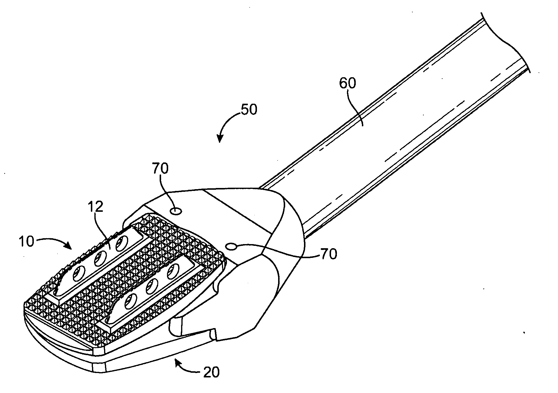
[0033]An intervertebral disc placement system according to the present invention includes a multi part disc and an associated placement instrument. The placement instrument holds the disc securely for placement into an intervertebral disc space and quickly releases the implant within the disc space.

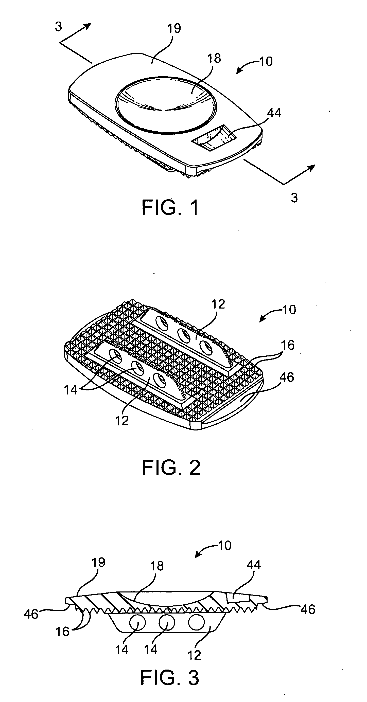
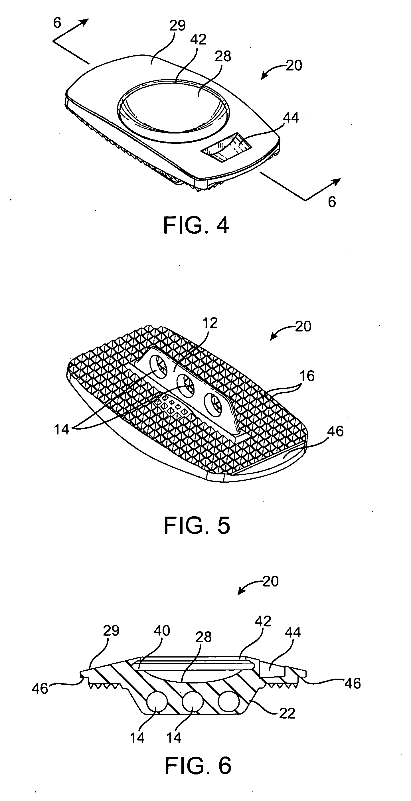
[0034]FIGS. 1-3 illustrate a superior or upper plate 10 of an intervertebral disc. FIGS. 4-6 illustrate a corresponding inferior or lower plate 20 and FIG. 7 illustrates a core 30 positionable between the plates to form a complete articulating intervertebral disc. The upper and lower plates 10, 20 include outer vertebral body contacting surfaces which are provided with attachment enhancing features to ensure bone integration. The attachment enhancing features shown include one or more fins and an array of serrations. In the embodiment shown the upper plate includes two fins 12 and the lower plate includes one fin 22. The fins 12, 22 can be an elongate fins pierced by one or more transvers...


PUM

PropertyMeasurementUnit
angleaaaaaaaaaa
angleaaaaaaaaaa
angleaaaaaaaaaa

Abstract

An intervertebral disc placement system includes a multi part intervertebral disc, such as a mobile core disc, and an associated placement instrument. The placement instrument holds the disc securely with the disc endplates angled for ease of placement of the disc into an intervertebral disc space and quickly releases the implant within the disc space. The disc includes upper and lower plates having notches in inner surfaces for engagement of the placement instrument. The placement instrument has a rotatable key configured to fit into the first and second notches to grasp the disc from the interior and eliminate the need for an external grasping mechanism which could interfere with disc placement.

Description

CROSS-REFERENCES TO RELATED APPLICATIONS[0001]This application claims priority to U.S. Provisional Application No. 61 / 018,441 filed Jul. 17, 2008, entitled “ARTIFICIAL INTERVERTEBRAL DISC PLACEMENT SYSTEM” the full disclosure of which is incorporated herein by reference.STATEMENT AS TO RIGHTS TO INVENTIONS MADE UNDER FEDERALLY SPONSORED RESEARCH AND DEVELOPMENT[0002]NOT APPLICABLEBACKGROUND OF THE INVENTION[0003]The present invention relates to medical devices and methods. More specifically, the present invention relates to intervertebral disc prostheses.[0004]Back pain takes an enormous toll on the health and productivity of people around the world. According to the American Academy of Orthopedic Surgeons, approximately 80 percent of Americans will experience back pain at some time in their life. On any one day, it is estimated that 5% of the working population in America is disabled by back pain.[0005]One common cause of back pain is injury, degeneration and / or dysfunction of one ...

Claims


Application Information

Patent Timeline
Patent Type & Authority Applications(United States)
IPC IPC(8): A61F2/44A61B17/58
CPCA61F2/30965A61F2310/0088A61F2/4611A61F2002/30617A61F2002/30649A61F2002/30662A61F2002/30663A61F2002/30843A61F2002/30884A61F2002/30892A61F2002/30899A61F2002/30906A61F2002/3093A61F2002/443A61F2002/4627A61F2002/4628A61F2250/0097A61F2310/00017A61F2310/00023A61F2310/00029A61F2310/00071A61F2310/00131A61F2310/00179A61F2310/00323A61F2310/00407A61F2310/00796A61F2/4425
Inventor JANSEN, NEVILLEDE VILLIERS, MALAN
Owner SIMPLIFY MEDICAL PTY LTD
Learn More