Method and system for determining residential fuel usage

a fuel consumption rate and residential technology, applied in the direction of instruments, lighting and heating equipment, machines/engines, etc., can solve problems such as system failure, and achieve the effect of accurately predicting consumption rates, eliminating attacks on the credibility of calculations, and high-quality pictures

Active Publication Date: 2010-01-21
CERTUSE JOHN
View PDF2 Cites 2 Cited by
  • Summary
  • Abstract
  • Description
  • Claims
  • Application Information

AI Technical Summary

Benefits of technology

[0017]Once a value is known of the amount of fuel that is used daily for domestic water usage and pilot flame usage, many arguments and assumptions can be overcome. For example, should a homeowner state that the reduction is the result of a three-week trip away from home, the fuel consumption calculation can be adjusted based on a three-week period where no domestic hot water was used. This allows a highly accurate picture of the fuel employed for heating only thereby eliminating attacks on the credibility of the calculation.
[0018]It is therefore an object of the present invention to provide a method and system that accurately predicts consumption rates in a residential structure. It is a further object of the present invention to provide a method and system that can more accurately determine the amount of fuel required to maintain a residential structure at a consistent temperature, thereby allowing identification of various system anomalies that may occur over time. It is still a further object of the present invention to provide a method and system that accounts for a number of fuel usage variables such as pilot light and domestic hot water usage in a manner that allows improved accuracy in determining the amount of fuel required to maintain a residential structure at a consistent temperature, thereby allowing identification of various system anomalies that may occur over time.

Problems solved by technology

For example, the analysis of such variations may indicate that the fuel ran out, the system failed, the existence of a fuel leak, an opening in the building envelope, etc.

Method used


Image

  • Method and system for determining residential fuel usage
  • Method and system for determining residential fuel usage
  • Method and system for determining residential fuel usage

Examples


Embodiment Construction

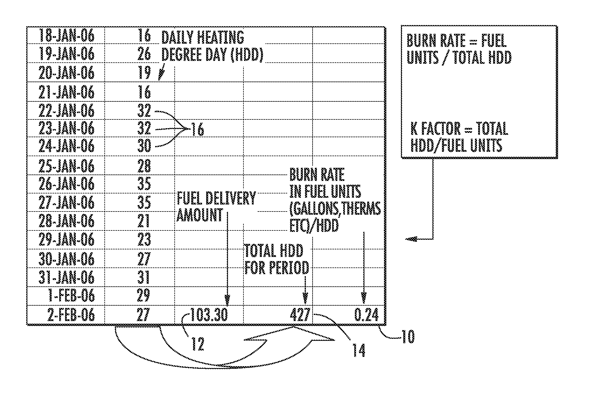
[0025]Now referring to the drawings, the method and system of the present invention is shown and generally illustrated in the figures. As stated above, the present invention provides for a method and system that allows the accurate prediction of fuel consumption rates in a residential structure in a manner that allows identification of various system anomalies. In operation the method and system employs a baseline calculation that determines an assumed fuel burn rate for a residential structure and then compares the baseline to the actual fuel consumed during a period of time to identify variations in consumption that can be further analyzed to determine the cause of the variations.

[0026]In operation, the method and system of the present invention provides first for the calculation of the burn rate for a given structure. As depicted in the chart at FIG. 1, the burn rate 10 is determined by dividing the total amount of fuel units delivered 12 to the structure over a given period divi...


PUM


Abstract

A method and system that accurately predicts fuel consumption rates in a residential structure is provided. The present invention more accurately determines the amount of fuel required to maintain a residential structure at a consistent temperature, thereby allowing identification of various system anomalies that may occur over time. Further, the method and system accounts for a number of fuel usage variables such as pilot light and domestic hot water usage in a manner that allows improved accuracy in determining the amount of fuel required to maintain a residential structure at a consistent temperature, thereby allowing identification of various system anomalies that may occur over time.

Description

CROSS-REFERENCE TO RELATED APPLICATIONS[0001]This application is related to and claims priority from earlier filed US Provisional Patent Application No. 61 / 081,859, filed Jul. 18, 2008.BACKGROUND OF THE INVENTION[0002]The present invention relates generally to a method and system for predicting fuel consumption rates in a residential structure. More specifically, the present invention provides a method and system for more accurately determining the amount of fuel required to maintain a residential structure at a consistent temperature, thereby allowing identification of various system anomalies that may occur over time.[0003]It is well known in the prior art that the fuel usage required for the maintenance of a constant temperature in a residential structure is an inverse function relative to the changes in the ambient outdoor temperature. In the most simplistic terms, as the ambient outdoor temperature decreases, the fuel consumption required to maintain the interior of the residen...

Claims


Application Information

Patent Timeline
Patent Type & Authority Applications(United States)
IPC IPC(8): G06F19/00
CPCG06Q50/06G06Q10/04
Inventor CERTUSE, JOHN
Owner CERTUSE JOHN
Why Eureka
Try Eureka