
Ergonomic handle

a handle and ergonomic technology, applied in the field of ergonomic handles, can solve the problems of cycling hands fatigue, perspiration of cycling hands which continuously contact, perspiration or sponge materials used in the prior, etc., and achieve the effect of reducing the negative effects of perspiration and reducing the fatigue of the user's hand

Inactive Publication Date: 2010-01-28
SELLE ITALA
View PDF13 Cites 0 Cited by
  • Summary
  • Abstract
  • Description
  • Claims
  • Application Information

AI Technical Summary

Benefits of technology

[0016]Accordingly, the aim of the present invention is to provide such a handle which is ergonomically improved with respect to prior like-use handles.
[0017]Within the scope of the above mentioned aim, a main object of the invention is to provide such a handle adapted to greatly reduce the fatigue of a user hand in a prolonged use of an implement, instrument or vehicle.
[0018]Another object of the present invention is to provide such a handle affording an optimum perspiration, thereby reducing negative effects of such a perspiration.
[0019]Yet another important object of the present invention is to provide such an ergonomic handle which can be used in a broad range of tools, implements and control elements in general.
[0020]Yet another object of the present invention is to provide such a handle construction which, owing to its specifically designed structural features, is very reliable and safe in operation.

Problems solved by technology

In an agonistic prolonged use of a bicycle, this causes the cyclist hands to be fatigued, since conventional handles do not afford a good distribution of the user weight on the user hands.
Another problem is the perspiration of the cyclist hands which continuously contact the handlebar handles.
For solving the above problem, perspirating or sponge materials have been used in the prior art, but with poor results, because of the fact that, in each case, a bicycle handlebar handle is associated with a perfectly impermeable element constituted by the handlebar tube or by an implement handle.
Moreover, the fatigue and perspiration due to a long use may cause a reduction of the user capability of proper controlling the vehicle.
Like problems and requirements are encountered in all prior handle types, in particular in those which are mounted on implements and tools for sports and working applications.

Method used


Image

  • Ergonomic handle
  • Ergonomic handle
  • Ergonomic handle

Examples


Embodiment Construction

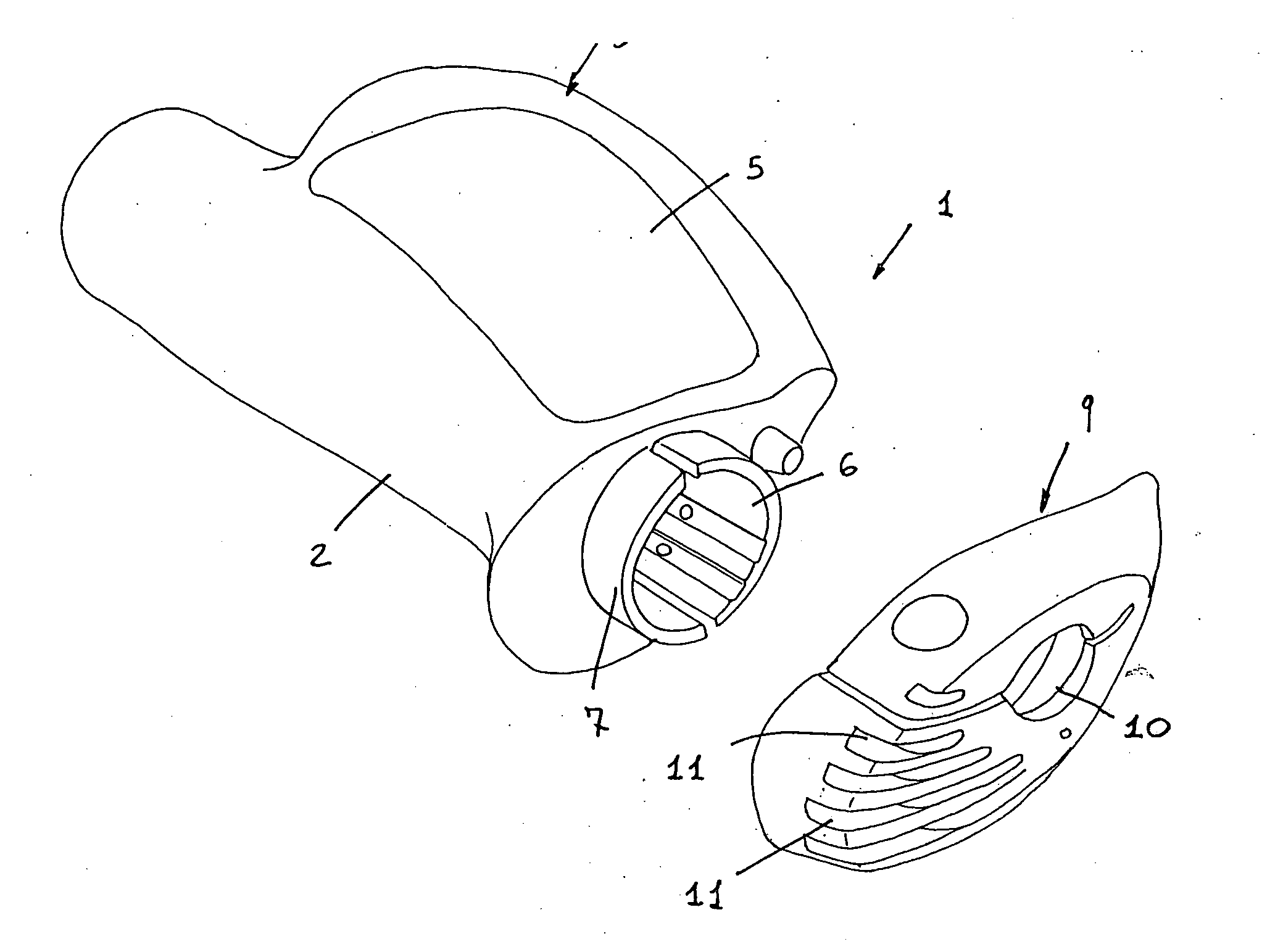
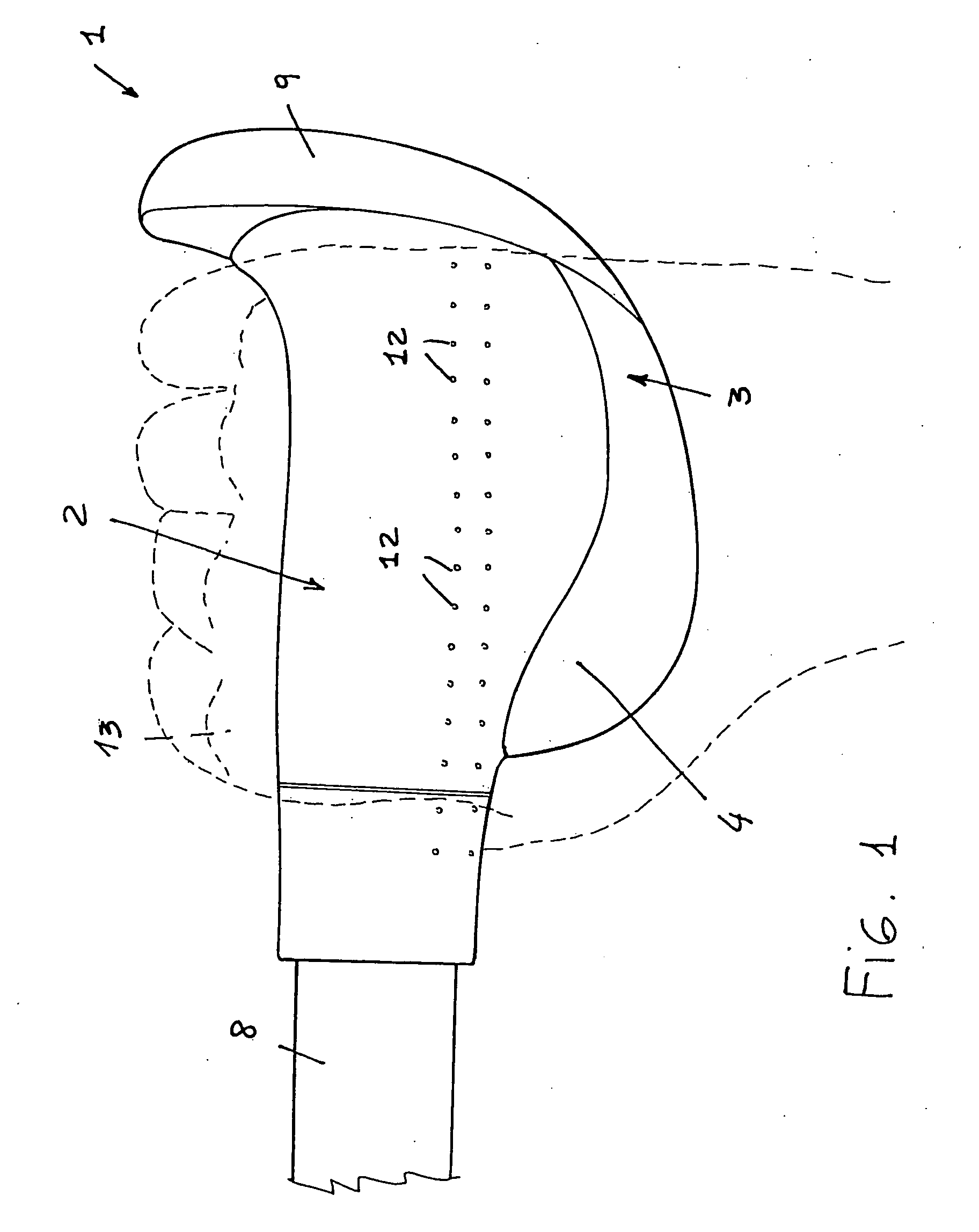
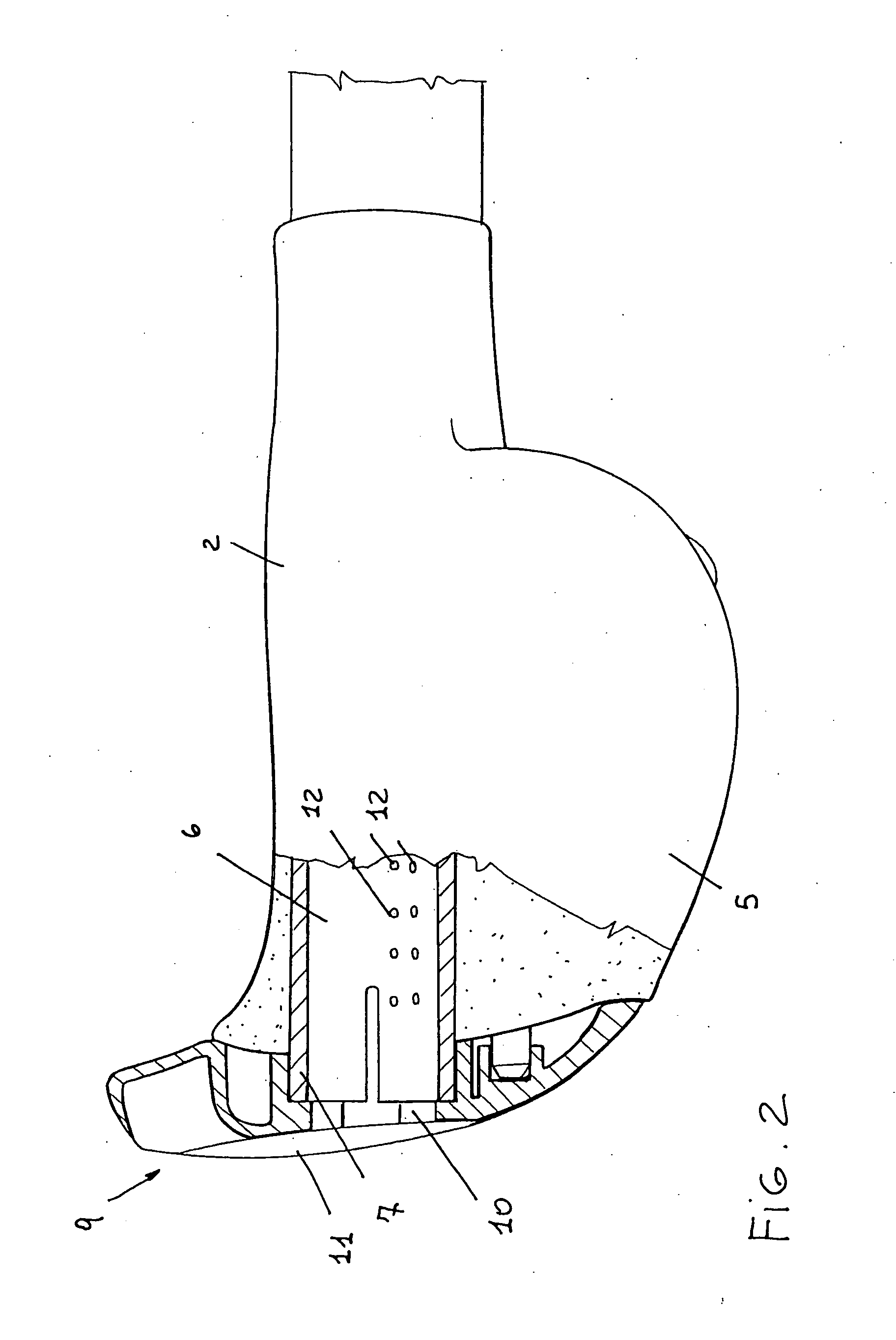
[0030]With reference to the number references of the above mentioned figures, the handle according to the invention, which has been generally indicated by the reference number 1, comprises a central body 2, meeting with a shaped or contoured portion 3, which extends, starting from the central body 2, to the rear of the handle, with reference to the advancing or running direction.

[0031]It should be apparent that the figures show a right handle.

[0032]The shaped or contoured portion 3 defines a top bearing surface 4, thereon a user hand can bear, and a bottom surface 5, defining a user finger gripping means.

[0033]Said central body 2 comprises a cavity 6, defined by a tubular element extending longitudinally within said central body and ending with a collar 7 at the outer end portion of the handle, that is at the handle end portion opposite to the handle portion associated or coupled to the handlebar 8.

[0034]Said collar 7 provides an engagement means for a terminal or end shaped element...


PUM


Abstract

An ergonomic handle comprises a handle central body coupled with a shaped portion extending from the central body to the rear of the handle with reference to a running direction, the shaped portion defining a top bearing surface thereon a hand of a user can bear and a bottom handle surface to be gripped by the user fingers, said handle further comprising ventilating means for allowing air to circulate therethrough.

Description

BACKGROUND OF THE INVENTION[0001]The present invention relates to an ergonomic handle.[0002]Handles of different constructions are used in several application fields, such as sports and working fields, to facilitate a gripping of an instrument, tool or control device to be gripped by the hands.[0003]In particular, handles are universally used on vehicles including handlebars such as bicycles, motorcycles, snowmobiles, watermobiles, and other sports and working implements such as barrows, shovels, and in all implements including a handle.[0004]Several types of handles are moreover used in sports and training implements, such as ski sticks, trekking sticks, handlebars for palestra training machines, and so on.[0005]Handles are furthermore used in working implements and instruments, which must be gripped for a long time, and for providing comparatively high efforts.[0006]For example, in the bicycle field, the handles applied at the end portions of the bicycle handlebar, facilitate a us...

Claims


Application Information

Patent Timeline
IPC IPC(8): B25G1/10
CPCA63B21/1434A63B49/08A63B59/0025A63B59/0029A63B59/0033Y10T16/476A63B71/14A63C11/222B25G1/102B62K21/26A63B59/0037A63B21/4017A63B60/12A63B60/10A63B60/16A63B60/18A63B60/08A63B60/14A63B60/00
Inventor BIGOLIN, RICCARDO
Owner SELLE ITALA
Learn More