Folding Wing Root Mechanism

a root mechanism and folding technology, applied in the direction of wing adjustment, aircraft stabilisation, aircraft convertible vehicles, etc., can solve the problems of non-backdrivability of the actuator, gaps, exposed mechanisms, etc., and achieve the effect of easy protection from the elements, long wing length, and high confiden

Active Publication Date: 2010-01-28
TERRAFUGIA
View PDF16 Cites 36 Cited by
  • Summary
  • Abstract
  • Description
  • Claims
  • Application Information

AI Technical Summary

Benefits of technology

[0013]The inner wing section is hinged to the vehicle along the bottom skin of the wing. Hinging at the bottom has advantages compared to hinging along the top of the wing. For example: the span of the wing can be longer for a given stowed wing size, and the folding mechanism can be made easily protected from the elements. The loads from the wing spar are transmitted to the body of the vehicle through the hinge on the bottom of the wing, and a retractable linkage on the top skin of the wing. A single linear actuator acting on the linkage can retract or deploy the wing, and in the deployed position, the linkage moves to an over-top-dead-center position, so wing load forces hold the linkage in the deployed position. Also there is a secondary locking mechanism preventing the linkage from folding, and the actuator is non-backdrivable. These three mechanisms provide a high level of confidence that the wing will not accidentally retract during flight activities. Another improvement embodied in this linkage is the ability of the pilot to perform both a direct visual and direct tactile check on its being in the locked position during the course of a standard pre-flight inspection of the aircraft. Furthermore, the wing has rigid panels that cover the hinge area when the wing is deployed, and the wing itself covers the hinge area when the wing is retracted. This is an improvement on other mechanisms because the vehicle is left with clean lines and a sealed hinge mechanism in both the retracted and deployed positions. Frequently folding wings leave exposed mechanism and open gaps in the retracted position.

Problems solved by technology

Also there is a secondary locking mechanism preventing the linkage from folding, and the actuator is non-backdrivable.
Frequently folding wings leave exposed mechanism and open gaps in the retracted position.

Method used


Image

  • Folding Wing Root Mechanism
  • Folding Wing Root Mechanism
  • Folding Wing Root Mechanism

Examples


Embodiment Construction

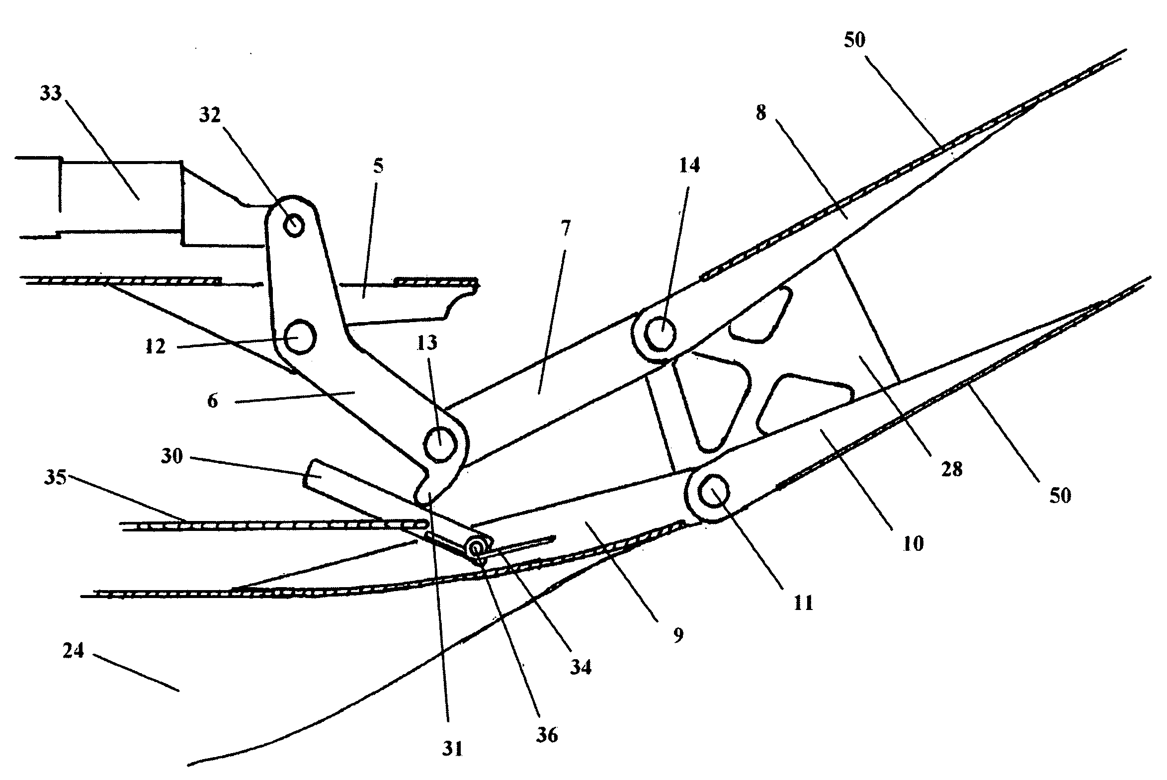
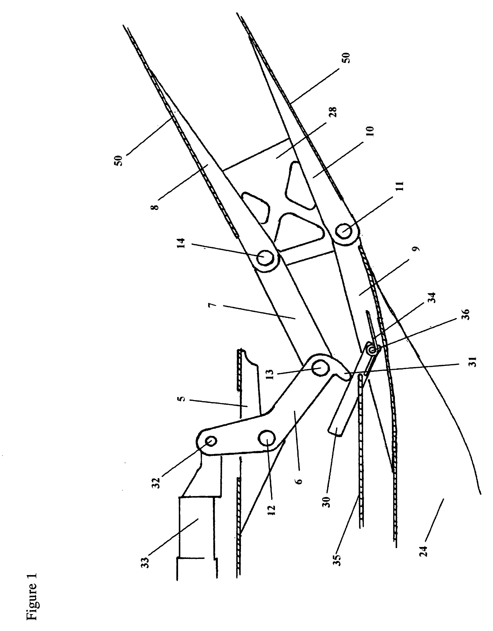
[0039]FIG. 1 shows the wing folding mechanism. In the preferred embodiment inner wing (50) is attached rigidly to hinge link no. 4 (8) and lower hinge wing side (10). Aircraft body (24) from which said wing will fold is mounted rigidly to hinge link no. 1 (5) and lower hinge base (9). Lower hinge base (9) and lower hinge wing side (10) are connected with lower hinge pin (11) so that the wing, attached to lower hinge wing side (10) can rotate about the axis created by lower hinge pin (11). The top half of the hinge mechanism consists of hinge link no. 1 (5) which is rigidly attached to the vehicle. Hinge link no. 2 (6) is allowed to rotate with respect to hinge link no 1 (5) using upper hinge pin no. 1 (12). The opposite end of hinge link no. 2 (6) is attached to hinge link no. 3 (7) with another hinge pin, upper hinge pin no. 2 (13). Hinge link no. 3 (7) is allowed to rotate with respect to upper hinge pin no. 2 (13), and is connected to hinge link no. 4 (8) with another hinge pin, ...


PUM


Abstract

Improvements to the hinge of a folding aircraft wing including a load bearing hinge mechanism with multiple locking mechanisms. The mechanism includes rigid panels that cover the hinge area when the wing is deployed, and the wing itself covers the hinge area when the wing is retracted. A control lever is used to actuate the wing and incorporates safety features to prevent unwanted actuation.

Description

FEDERALLY SPONSORED RESEARCH [0001]Not ApplicableSEQUENCE LISTING OR PROGRAM [0002]Not ApplicableFIELD OF THE INVENTION[0003]This invention relates to aircraft and to roadable aircraft, a type of aircraft that can be converted into an automotive type vehicle capable of driving on the road, sometimes popularly referred to as a “flying car” or “flying-driving vehicle”.BACKGROUND OF THE INVENTION[0004]This invention, though extensible to a broader spectrum of applications, was motivated by the development of a roadable aircraft. One of the challenges of developing a practical roadable aircraft is how to safely and securely stow the wings while operating in the road environment. Conveniently stowing a roadable or non-roadable aircraft's wings for storage could be accomplished with the same or similar techniques. This invention represents an improved method for accomplishing this.[0005]A common method for stowing the wings of a roadable aircraft described in prior art is to rotate the wi...

Claims


Application Information

Patent Timeline
Patent Type & Authority Applications(United States)
IPC IPC(8): B64C3/56
CPCB64C3/56B60F5/02
Inventor SCHWEIGHART, SAMUEL ADAMDIETRICH, CARL CURTISHEAFITZ, ANDREW
Owner TERRAFUGIA
Why Eureka
Try Eureka