Image signal processing apparatus, image signal processing method and video display apparatus
- Summary
- Abstract
- Description
- Claims
- Application Information
AI Technical Summary
Benefits of technology
Problems solved by technology
Method used
Image

Examples
first embodiment
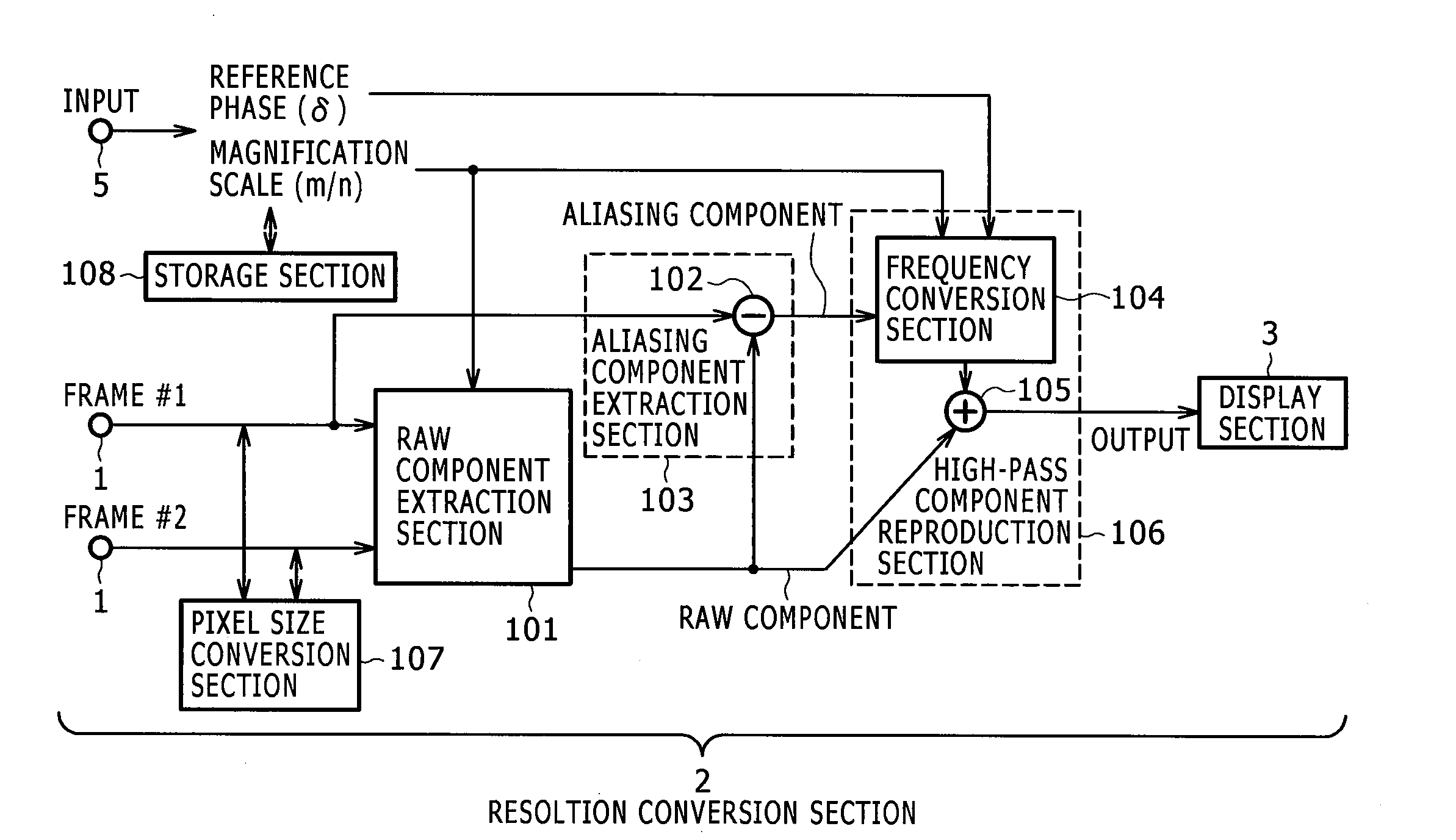
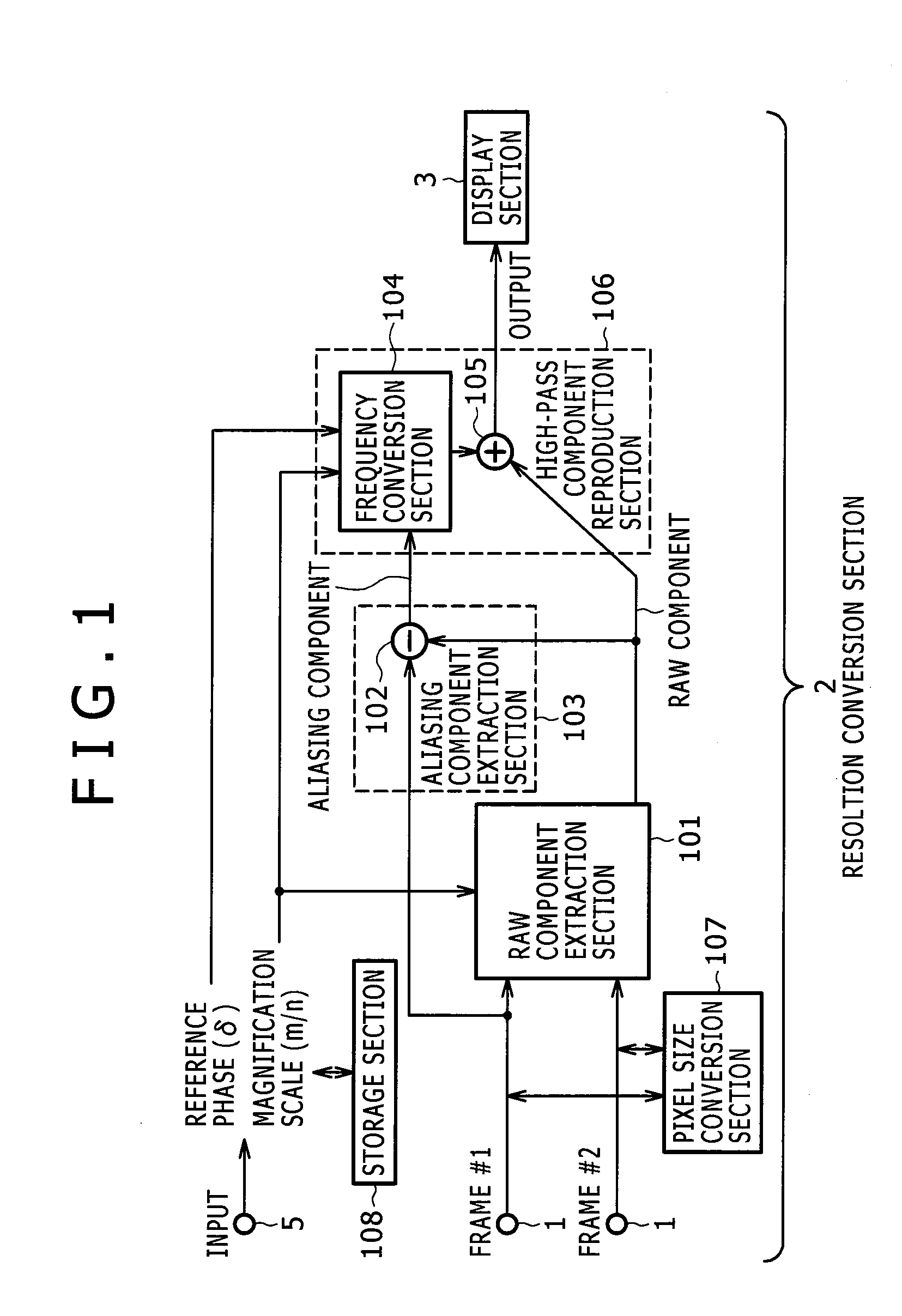
[0059]FIG. 1 shows an image signal processing apparatus according to the first embodiment of the invention. Features of the image signal processing apparatus will be described. The image signal processing apparatus according to the embodiment is applied to video display apparatuses such as television sets. A video display apparatus will be described as an example of the image signal processing apparatus in the following embodiments.
[0060]In FIG. 1, the image signal processing apparatus according to the embodiment includes an input section (1), a resolution conversion section (2), and a display section (3). The input section (1) is supplied with frame sequences of a moving image such as television broadcast signals, for example. The resolution conversion section (2) improves the resolution of frames supplied from the input section (1). The display section (3) displays an image based on the frames whose resolution is improved by the resolution conversion section (2). The input section...
second embodiment
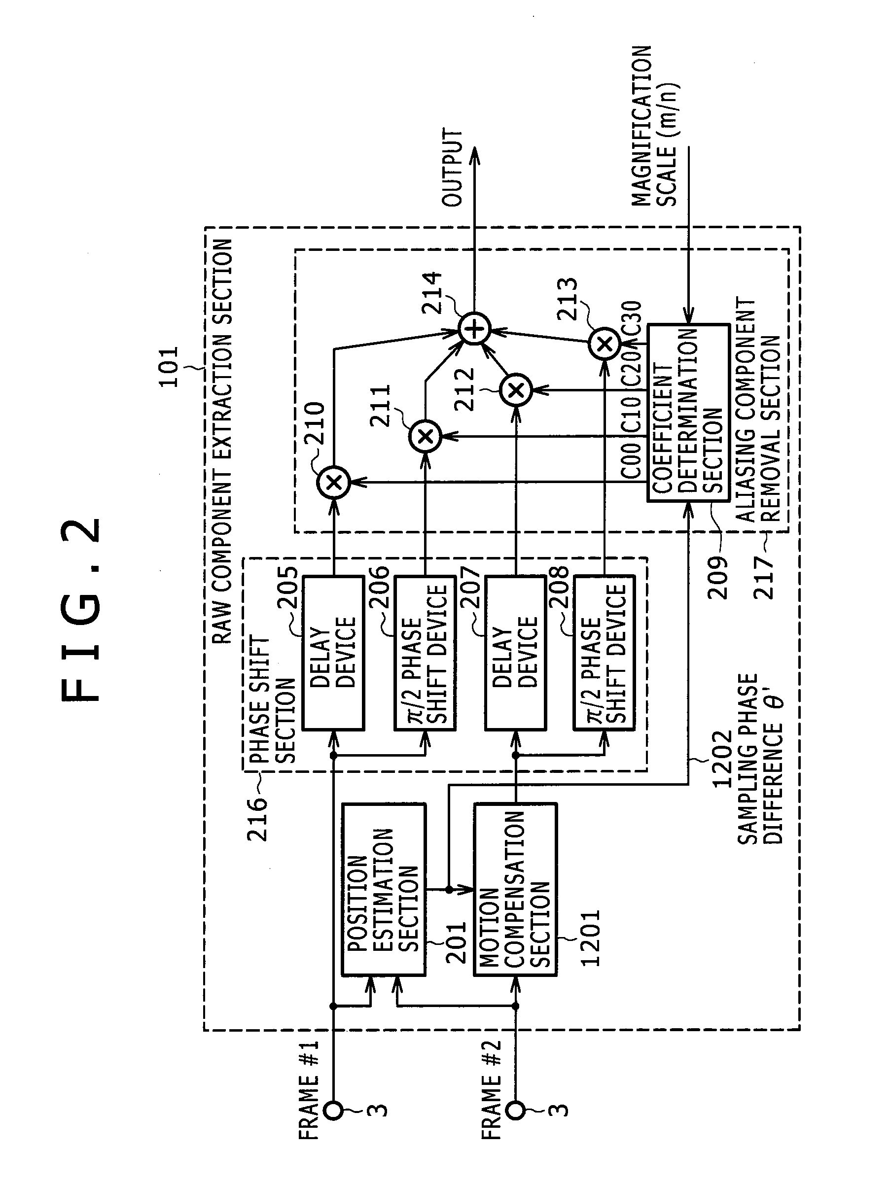
[0105]The second embodiment of the invention will be described with reference to FIGS. 12 through 15D. The second embodiment uses another configuration for operations equivalent to those of the resolution conversion section (2) according to the first embodiment. The following describes in detail the specific configuration and operations.
[0106]Operations of the sections in the raw component extraction section (101) in FIG. 12 are the same as the counterparts according to the first embodiment and the description is omitted for simplicity. Folded component extraction sections (1203) and (1210) are configured similarly to the aliasing component removal section (217). A coefficient determination section (1209) generates coefficients C02, C12, C22, and C32. A coefficient determination section (1216) generates coefficients C03, C13, C23, and C33. By configuring these coefficients to be described later, the aliasing component extraction sections (1203) and (1210) extract aliasing components...
third embodiment
[0115]The third embodiment of the invention uses a raw component extraction section (2014) shown in FIG. 20 instead of the raw component extraction section (101) in the configuration of the image signal processing apparatus as shown in FIG. 1. The embodiment provides the image signal processing apparatus that improves the resolution using three input frame images.
[0116]Operations of the raw component extraction section (2014) provide an improvement of the technology described in Japanese Published Unexamined Patent Application No. Hei 8-336046. Operations of the conventional technology described in Japanese Published Unexamined Patent Application No. Hei 8-336046 will be first described with reference to FIGS. 17A through 17C. As shown in FIGS. 17A through 17C, the technology described in Japanese Published Unexamined Patent Application No. Hei 8-336046 cancels aliasing components using signals for three frames #1, #2, and #3 to extract only raw signals (1701), (1702), and (1703). T...
PUM
 Abstract
Description
Claims
Application Information
 - R&D
- Intellectual Property
- Life Sciences
- Materials
- Tech Scout
- Unparalleled Data Quality
- Higher Quality Content
- 60% Fewer Hallucinations
Browse by: Latest US Patents, China's latest patents, Technical Efficacy Thesaurus, Application Domain, Technology Topic, Popular Technical Reports.
© 2025 PatSnap. All rights reserved.Legal|Privacy policy|Modern Slavery Act Transparency Statement|Sitemap|About US| Contact US: help@patsnap.com