
System for reducing acoustic feedback in hearing aids using inter-aural signal transmission, method and use

a technology of inter-aural signal transmission and hearing aid, applied in the field of hearing aid, can solve the problems of signal distortion, autocorrelation of input signal to correlation between, and inability to accurately eliminate and achieve the effect of reducing or eliminating acoustic feedback in a pair

Active Publication Date: 2010-01-28
OTICON
View PDF7 Cites 26 Cited by
  • Summary
  • Abstract
  • Description
  • Claims
  • Application Information

AI Technical Summary

Benefits of technology

[0021]An advantage of the invention that it provides a scheme for reducing or effectively eliminating acoustic feedback in a pair of hearing instruments.
[0022]The term ‘originating from the electric input signal’ is in the present context taken to mean a signal based on or derived from (e.g. an attenuated or amplified version of) the electric input signal from the input transducer, e.g. an analog output signal from the input transducer, or a digitized version thereof (e.g. from an A / D-converter connected to the input transducer), or a processed version of the electric input signal, e.g. wherein directional information has been extracted or, ultimately, wherein the electric input signal has been processed in a digital signal processor and e.g. adapted to a users hearing profile (e.g. in the form of the processed output signal as forwarded to an output transducer). In general, the term ‘signal-1 originating from signal-2’ may indicate that signal-1 is based on or derived from (e.g. an attenuated or amplified otherwise modified version of) signal-2. The term ‘signal-1 originating from signal-2’ may indicate that the source of signal-1 (e.g. the output of a functional block or component) is electrically connected to the destination of signal-2 (e.g. the input of a functional block or component). The term ‘originating from’ may indicate ‘equal to’ (e.g. that the signals are substantially identical).
[0023]The term ‘used in the formation of’ is here understood to mean e.g. ‘added to’ or subtracted from or ‘multiplied by’ or otherwise combined with the original signal to form the signal in question (e.g. including a further processing of the original signal). The term ‘signal-1 is used in the formation of signal-2’ may indicate that the source of signal-1 is electrically connected to the destination of signal-2. The term ‘used in the formation of’ may indicate ‘equal to’ (i.e. that the signals are identical).
[0024]The term ‘hearing instruments’ is in the present context taken to include hearing devices comprising a microphone, a frequency dependent gain of the microphone signal to be presented to a user by a receiver (speaker).
[0025]The term ‘spatially separated’ is taken to mean a certain physical distance apart, e.g. at least 0.1 m apart. In an embodiment, the first and second hearing instruments are ‘spatially separated’, if located on different parts of a person's body, e.g. one at an ear and another around the neck or at or in a pocket, or e.g. on each side of a head of a user, e.g. at or in the respective ears of the user. In an embodiment, the first (second) input transducer is spatially separated from the second (first) output transducer in that the distance between them, when the system is in operation, is larger than 0.05 m, such as in the range from 0.05 m to 0.2 m. In an embodiment, the first (second) input transducer is spatially separated from the second (first) output transducer in that the distance between them, when the system is in operation, is less than 1 m e.g. less than 0.5 m.
[0026]In a preferred embodiment, the first and / or second Tx-signals comprise the full audio frequency range considered by the hearing instrument, e.g. the frequency range between 20 Hz and 12 kHz. Alternatively, the first and / or second Tx-signals comprise a part of the full audio frequency range considered by the hearing instrument, such as e.g. one or more specific frequency ranges or bands, e.g. the relatively low frequency ranges (e.g. frequencies below 1 500 or 1000 Hz) or the relatively high frequency ranges (e.g. frequencies above 2000 or 4 000 Hz).

Problems solved by technology

The acoustic leakage from the receiver to the microphone of a hearing aid (in particular such hearing aids where microphone and receiver are located at a short distance from each other) may lead to feedback instability or oscillation when the gain in hearing aid is increased above a certain point.
However, unfortunately in hearing aid applications the output and input signals are typically not uncorrelated, since the output signal is in fact a delayed (and processed) version of the input signal; consequently, autocorrelation in the input signal leads to correlation between the output signal and the input signal.
If correlation exists between these two signals, the feedback cancellation filter will not only reduce the effect of feedback, but also remove components of the input signal, leading to signal distortions and a potential loss in intelligibility (in the case that the input signal is speech) and sound quality (in the case of audio input signals).

Method used


Image

  • System for reducing acoustic feedback in hearing aids using inter-aural signal transmission, method and use
  • System for reducing acoustic feedback in hearing aids using inter-aural signal transmission, method and use
  • System for reducing acoustic feedback in hearing aids using inter-aural signal transmission, method and use

Examples


Embodiment Construction

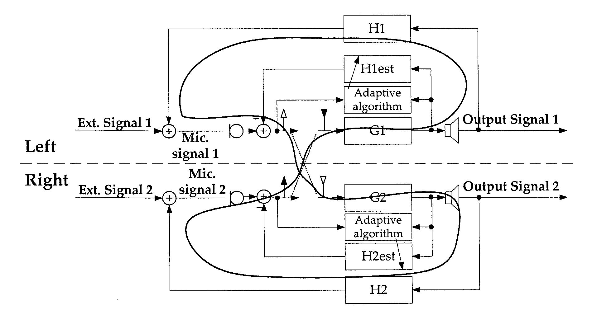
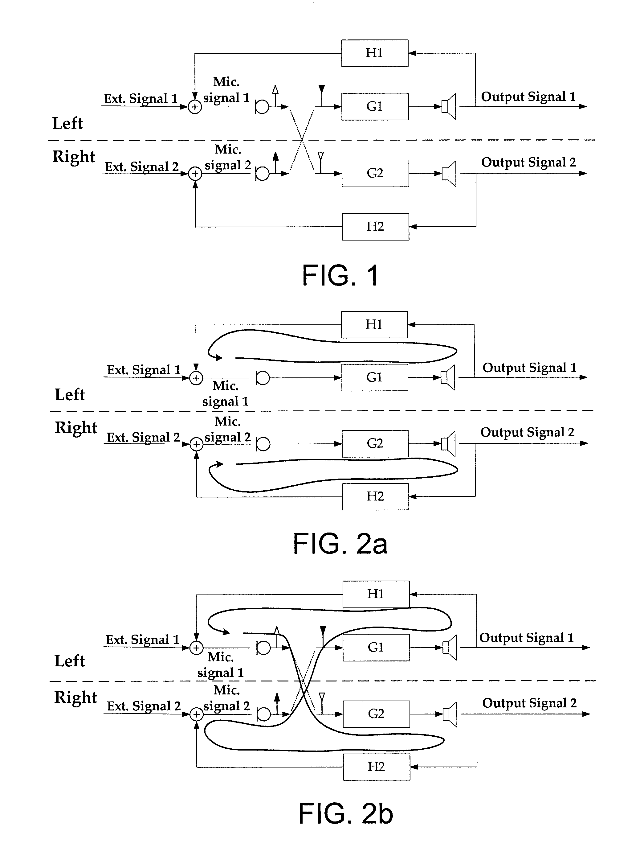
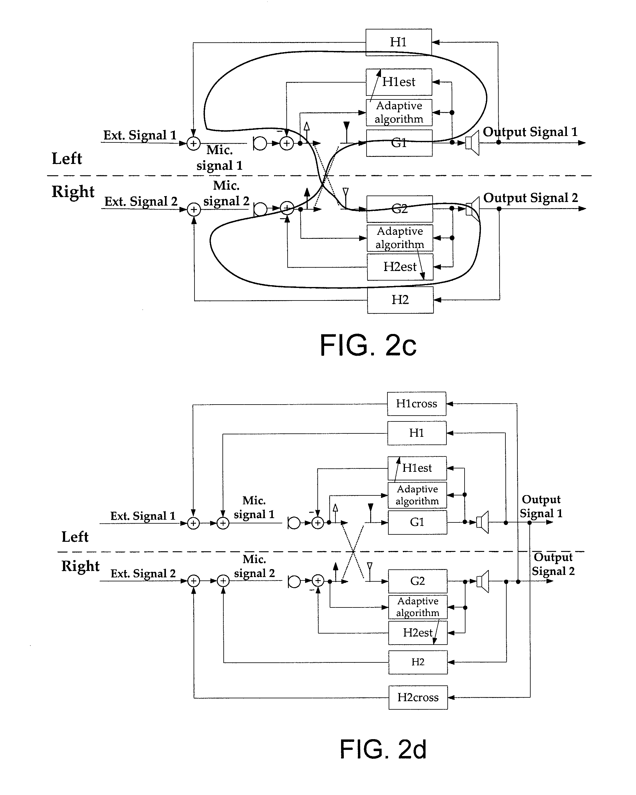
[0075]FIG. 4 shows a simplified block diagram of a hearing aid comprising a conventional feedback cancellation system for reducing or cancelling acoustic feedback from an ‘external’ feedback path (termed ‘Acoustic Feedback’ in FIG. 4) from an output to an input transducer of the hearing aid. The feedback cancellation system comprises an adaptive filter, which is controlled by a prediction error algorithm, e.g. an LMS (Least Means Squared) algorithm, in order to predict and cancel the part of the microphone signal that is caused by feedback from the receiver of the hearing aid. The adaptive filter (in FIG. 4 comprising a ‘Filter’ part end a prediction error ‘Algorithm’ part) is aimed at providing a good estimate of the ‘external’ feedback path from the digital to analogue converter DA to the analogue to digital converter AD. The prediction error algorithm uses a reference signal together with the (feedback corrected) microphone signal to find the setting of the adaptive filter that m...


PUM


Abstract

The invention relates to a hearing aid system comprising first and second spatially separated hearing instruments, the system being adapted for processing input sounds to output sounds according to a user's needs. The invention further relates to a method and use. The object of the present invention is to provide an alternative scheme for reducing the effect of acoustic feedback in a hearing aid system. The problem is solved in that the hearing instruments comprises, respectively, first and second input transducers for converting a first input sound to first and second electric input signal, and first and second output transducers for converting first and second processed electric output signal to first and second output sounds, wherein the system is adapted to provide that a first Tx-signal originating from the first electric input signal of the first hearing instrument is transmitted to the second hearing instrument and used in the formation of the second processed electric output signal, and that a second Tx-signal originating from the second electric input signal of the second hearing instrument is transmitted to the first hearing instrument and used in the formation of the first processed electric output signal. This has the advantage of providing a scheme for reducing or effectively eliminating acoustic feedback in a pair of hearing instruments. The invention may e.g. be used in listening devices, e.g. hearing aids, head sets, or active ear plugs.

Description

TECHNICAL FIELD[0001]The invention relates to feedback cancellation in listening devices. The invention relates specifically to a hearing aid system comprising first and second spatially separated hearing instruments, the system being adapted for processing input sounds to output sounds according to a user's needs.[0002]The invention furthermore relates to a method of reducing acoustic feedback in a hearing aid system comprising first and second hearing instruments, each for processing an input sound to an output sound according to a user's needs and to use of a hearing aid system.[0003]The invention may e.g. be useful in applications such as listening devices, e.g. hearing aids, headsets or active ear plugs.BACKGROUND ART[0004]The following account of the prior art relates to one of the areas of application of the present invention, hearing aids.[0005]The acoustic leakage from the receiver to the microphone of a hearing aid (in particular such hearing aids where microphone and rece...

Claims


Application Information

Patent Timeline
IPC IPC(8): H04R25/00
CPCH04R5/033H04R25/552H04R25/453
Inventor ELMEDYB, THOMAS BOJENSEN, JESPERGUO, MENG
Owner OTICON
Learn More