Apparatus and method for forming annular grooves on the outer surface of a cable or tube

a technology of annular grooves and outer surfaces, which is applied in the direction of driving apparatuses, milling equipments, worms, etc., can solve the problems of premature failure of bearings, significant decrease in the operating life of bearings, and difficulty in processing small tubes, so as to reduce the time taken and produce convenient

Active Publication Date: 2010-01-28
PPC BROADBAND FIBER LTD
View PDF7 Cites 18 Cited by
  • Summary
  • Abstract
  • Description
  • Claims
  • Application Information

AI Technical Summary

Benefits of technology

[0021]A further advantage of the present invention is that the cutter may accommodate a wide range of tube diameters and this will reduce the time taken to change production from a first diameter of tube to a second diameter of tube. For the production of tubes which are to receive optical fibres, which will typically have an outer diameter of 1 to 10 mm, then it is believed that this size range can be readily produced using the same cutter. It will be understood that the separation of the first and second positioning rollers from the interior wall of the cylindrical cutter will vary with the outer diameter of the tube. Accordingly, the apparatus may allow the position of the first and second positioning rollers to be varied in order to accept a tube of a given diameter. Alternatively, the first and second positioning rollers may be replaced with positioning rollers having different diameter to accommodate the tube. The positioning and or size of the control rollers must also be variable in order to retain the contact between the first and second positioning rollers and the first and second control rollers.

Problems solved by technology

One of the limitations of the apparatus disclosed in EP 765 214 is that the triangular arrangement of the rollers form an interstice through which the tube is passed.
The geometry of this arrangement means that it is difficult to process small tubes, for example tubes having a diameter of 3 mm or less.
One of the disadvantages of the approaches disclosed in both EP 765 214 and GB 0421439.1, is that in order to form grooves small diameter tubes, it is necessary to use small bearings to rotate the rollers that form the grooves.
Prolonged operation at these sorts of speeds leads to a significant decrease in the operating lifetime of the bearings.
It has believed that the centrifugal forces cause the lubricant within the bearings to be expelled past the seals, which leads to the premature failure of the bearings.

Method used


Image

  • Apparatus and method for forming annular grooves on the outer surface of a cable or tube
  • Apparatus and method for forming annular grooves on the outer surface of a cable or tube
  • Apparatus and method for forming annular grooves on the outer surface of a cable or tube

Examples


Embodiment Construction

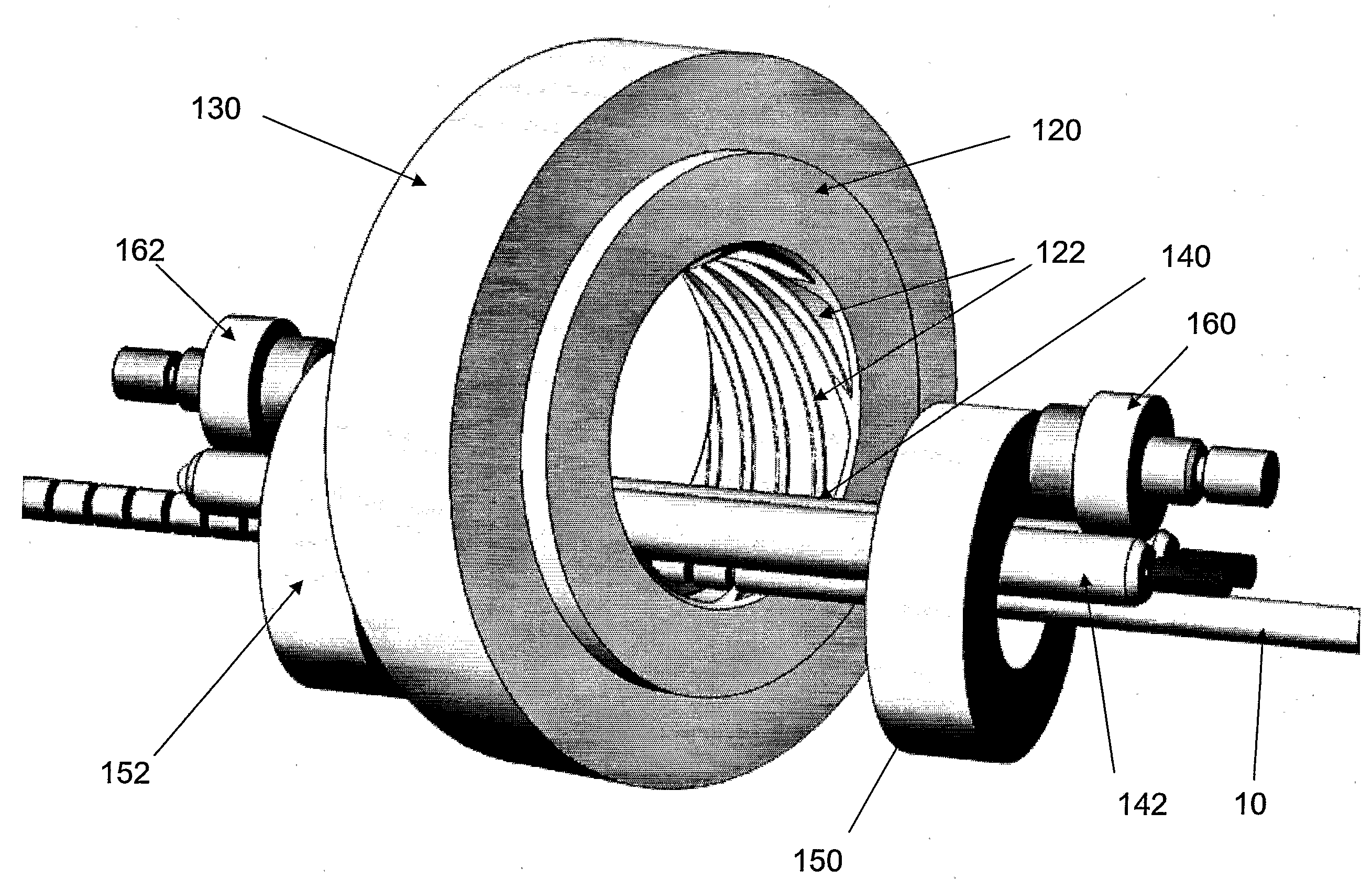
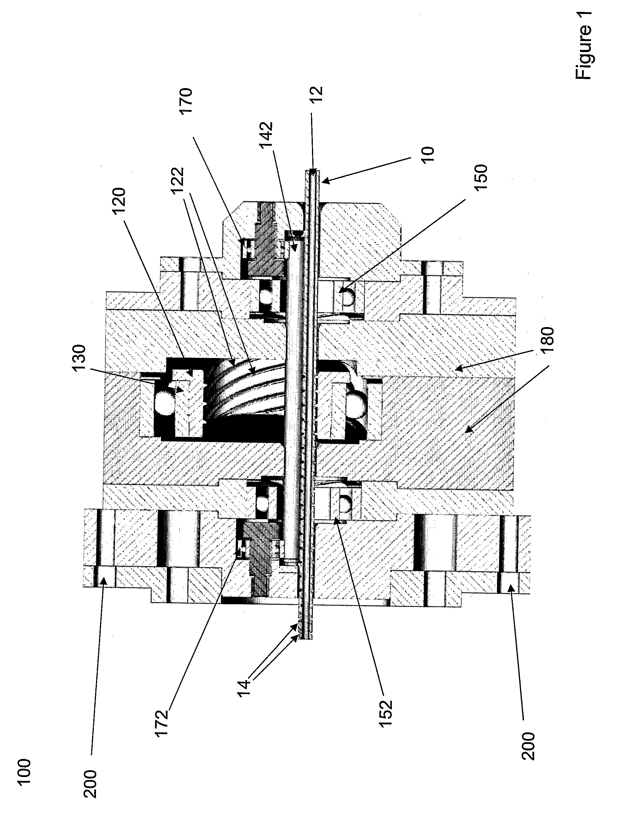
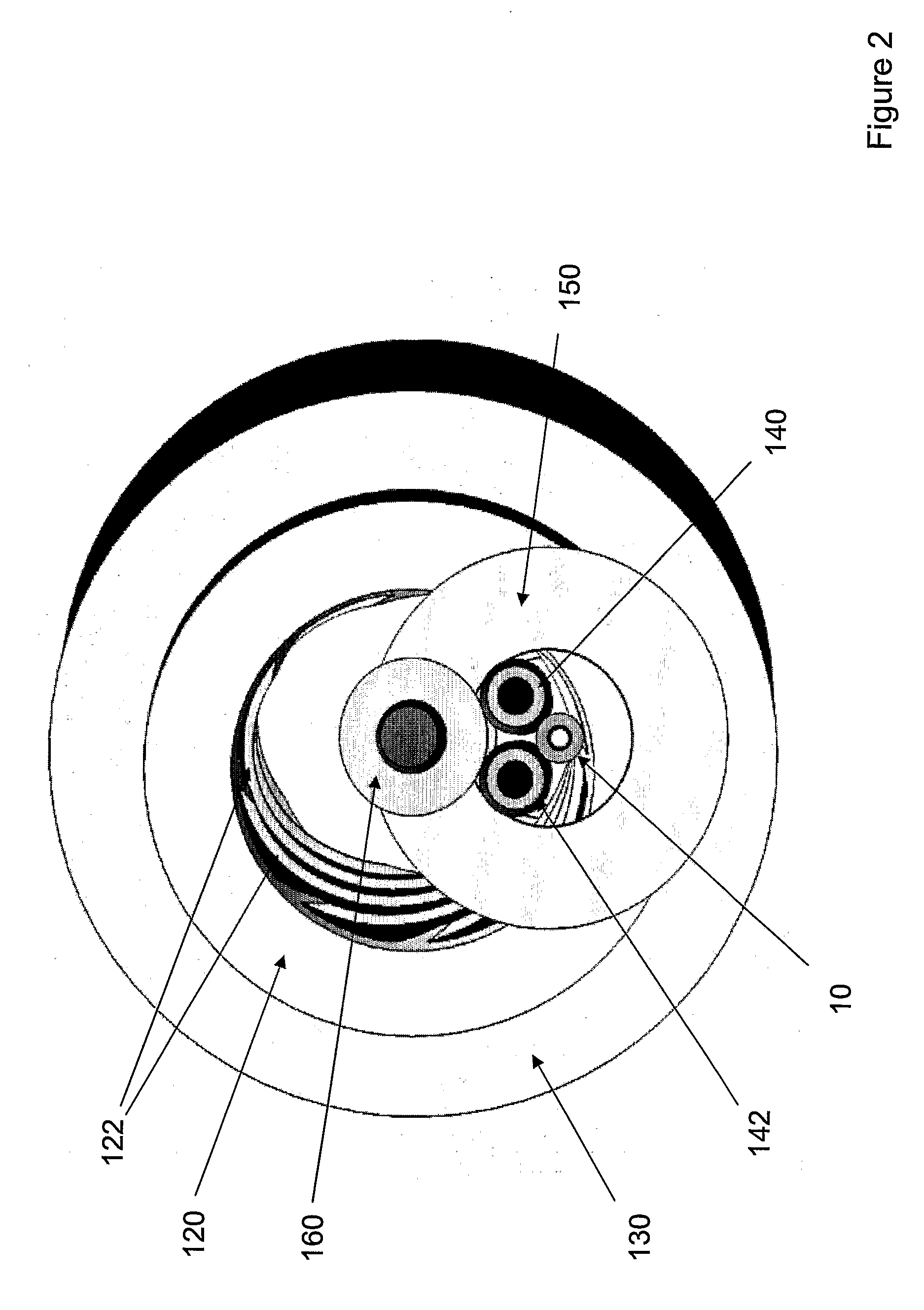
[0016]FIGS. 1 to 4 show a schematic depiction of an apparatus 100 according to the present invention: FIG. 1 shows a cross-section of the apparatus; FIG. 2 shows a cut-away axial view of the apparatus; FIG. 3 shows a cut-away perspective view of the apparatus; and FIG. 4 shows a cut-away side view of the apparatus.

[0017]The apparatus 100 comprises a rotatable cylindrical cutter 120, which is received within and coupled to a cutter bearing 130. The inner surface of the rotatable cylindrical cutter comprises a plurality of cutting edges 122. Received within the interior of the rotatable cylindrical cutter are first and second positioning rollers 140&142. which extend beyond either end of the rotatable cylindrical cutter. First and second positioning bearings 150&152 are provided at the first and second ends of the first and second positioning rollers, the first and second positioning bearings being located outside of the rotatable cylindrical cutter. The first and second positioning b...


PUM

PropertyMeasurementUnit
angleaaaaaaaaaa
angleaaaaaaaaaa
angleaaaaaaaaaa

Abstract

The present invention provides an apparatus (100) for forming circumferential grooves (14) in the exterior surface of a linear member (10), such as a tube. The grooves are formed by rotating a cylindrical cutting element (120) around the tube such that cutting means in the cylindrical cutting element form the grooves. One rotation of the cylindrical cutting element causes multiple grooves to be formed in the surface of the tubes.

Description

BACKGROUND[0001]a. Field of the Invention[0002]The present invention relates to the processing of linear members such as cables or tubes, and in particular to apparatuses for and methods of processing linear members to form a series of annular grooves in their outer surfaces.[0003]b. Related Art[0004]EP 765 214 discloses an apparatus suitable for forming a series of parallel grooves in the outer wall of a smooth bore tube. The apparatus comprises three rollers which are disposed around the tube as it is passed through the apparatus. One or more of the rollers are grooved and the rotation of the grooved roller(s) forms the sequence of grooves within the outer surface of the tube.[0005]One of the limitations of the apparatus disclosed in EP 765 214 is that the triangular arrangement of the rollers form an interstice through which the tube is passed. The geometry of this arrangement means that it is difficult to process small tubes, for example tubes having a diameter of 3 mm or less.[...

Claims


Application Information

Patent Timeline
Patent Type & Authority Applications(United States)
IPC IPC(8): B23C3/32B29C59/04B21D17/04B21C37/20B21D13/04B21D15/04
CPCB21D13/04B21D15/04B21D17/04Y10T409/300056Y10T409/309184Y10T409/305656Y10T409/305768Y10T409/300672B21C37/20B23C3/32
Inventor JENKINS, PETER DAVIDJENKINS, DANIEL OWEN
Owner PPC BROADBAND FIBER LTD
Why Eureka
Try Eureka