Methods and apparatus for locking a band

a technology of locking and band, applied in the field of medical methods and equipment, can solve the problems of limiting the translation of the roller along its axis, the translation of the thread, etc., and achieve the effects of reducing the flexion of at least one, less invasive, and convenient operation

Active Publication Date: 2010-01-28
SIMPIRICA SPINE
View PDF100 Cites 43 Cited by
  • Summary
  • Abstract
  • Description
  • Claims
  • Application Information

AI Technical Summary

Benefits of technology

[0017]The present invention provides fastening mechanisms and methods for releasably locking an implantable surgical tether. Exemplary orthopaedic applications include restricting flexion of at least one spinal segment or securing broken bones together. More particularly, the provided fastening mechanisms and methods relate to improvements to t

Problems solved by technology

Although the purpose of the alignment feature is to constrain rotation of the roller, it may directly limit translation of the roller along its axis, for example when the rolle

Method used


Image

  • Methods and apparatus for locking a band
  • Methods and apparatus for locking a band
  • Methods and apparatus for locking a band

Examples


Embodiment Construction

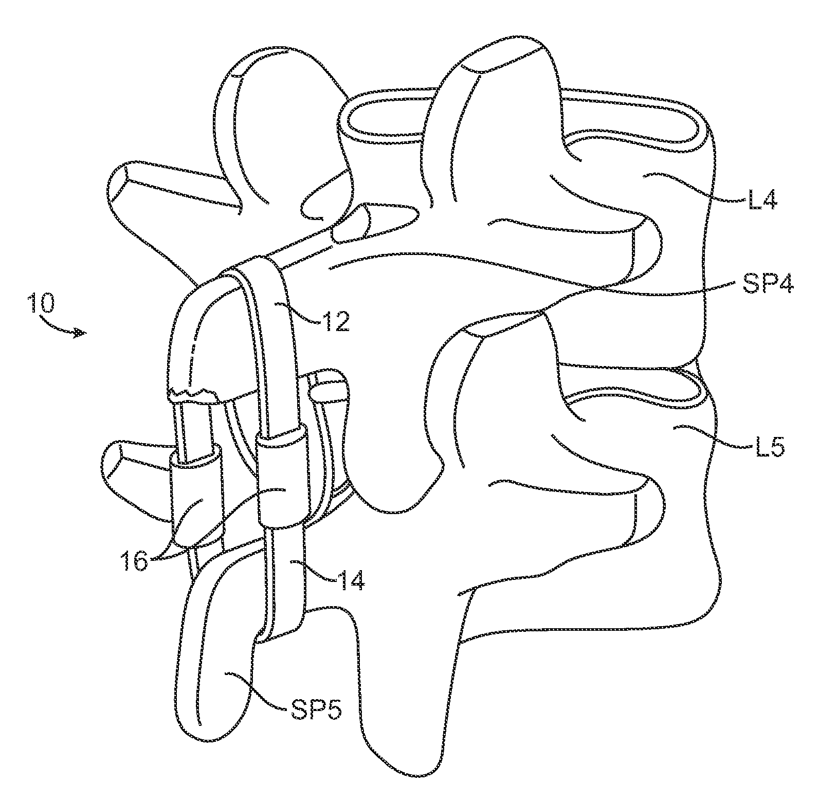
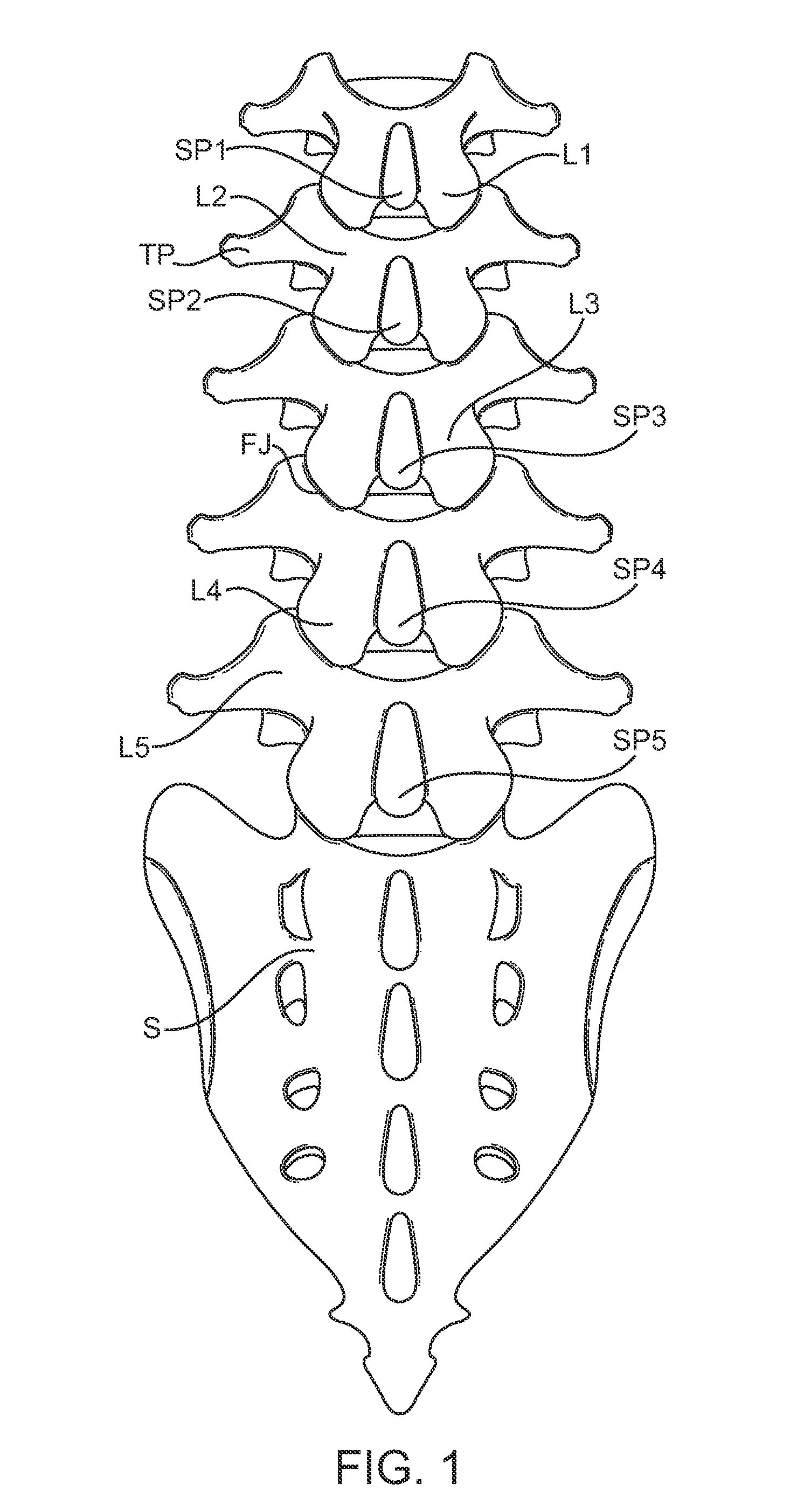
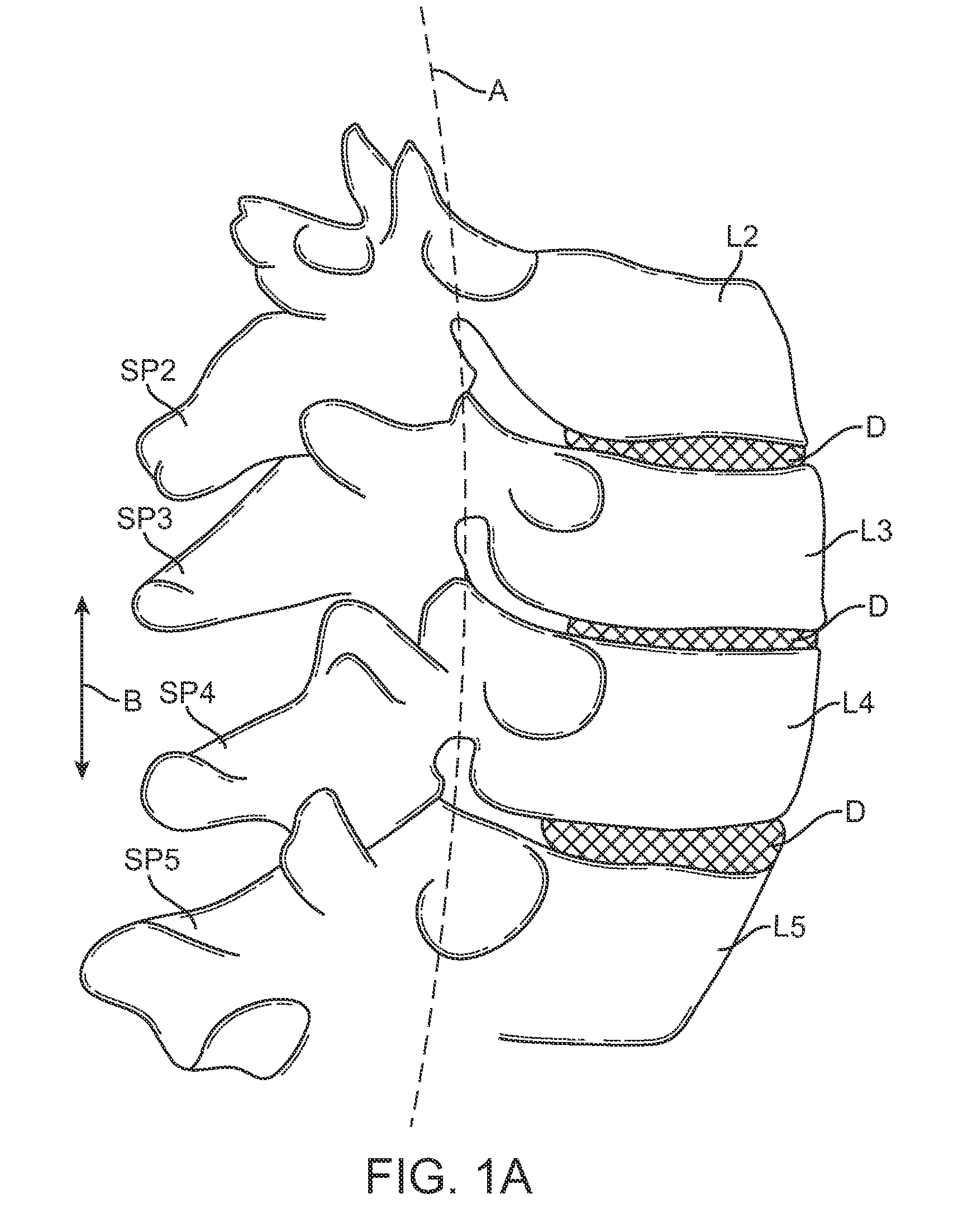
[0040]FIG. 1 is a schematic diagram illustrating the lumbar region of the spine including the spinous processes (SP), facet joints (FJ), lamina (L), transverse processes (TP), and sacrum (S). FIG. 1A is a schematic illustration showing a portion of the lumbar region of the spine taken along a sagittal plane and is useful for defining the terms “neutral position,”“flexion,” and “extension” that are often used in this disclosure.

[0041]As used herein, “neutral position” refers to the position in which the patient's spine rests in a relaxed standing position. The “neutral position” will vary from patient to patient. Usually, such a neutral position will be characterized by a slight curvature or lordosis of the spine where the spine has a slight anterior convexity and slight posterior concavity. In some cases, the presence of the constraint of the present invention may modify the neutral position, e.g. the device may apply an initial force which defines a “new” neutral position having so...


PUM


Abstract

A surgical fastening mechanism for releasably locking an implantable tether includes a housing having a central channel. The housing has an entry aperture, an exit aperture and a side channel extending therebetween. A roller element has a sidewall with an aperture therethrough and the roller is slidably disposed at least partially in the central channel such that the entry and exit apertures are at least partially aligned with the roller aperture. This permits passage of the tether therethrough. Rotation of the roller element in a first direction winds the tether around the roller thereby creating a friction interface between the roller element, the housing and the tether. A locking mechanism is operably connected with either the housing or the roller element and is adapted to prevent rotation of the roller in the central channel and also adapted to prevent release of the tether from the roller.

Description

CROSS-REFERENCES TO RELATED APPLICATIONS[0001]The present application is a non-provisional of, and claims the benefit of priority under 35 U.S.C. §119(e) of U.S. Provisional Application No. 61 / 059,538 (Attorney Docket No. 026398-000700US) filed Jun. 6, 2008, the entire contents of which are incorporated herein by reference.STATEMENT AS TO RIGHTS TO INVENTIONS MADE UNDER FEDERALLY SPONSORED RESEARCH AND DEVELOPMENT[0002]NOT APPLICABLEBACKGROUND OF THE INVENTION[0003]1. Field of the Invention[0004]The present invention generally relates to medical methods and apparatus. More particularly, the present invention relates to orthopedic internal fixation such as methods and devices for restricting spinal flexion in patients having back pain or for providing fracture fixation in long bone and trochanteric fractures or other orthopedic applications where a tether may be employed.[0005]A major source of chronic low back pain is discogenic pain, also known as internal disc disruption. Patients...

Claims


Application Information

Patent Timeline
IPC IPC(8): A61B17/70
CPCA61B17/7062A61B17/842A61B17/7053A61B17/82A61B17/8869
Inventor BENNETT, IANFIELDING, LOUISMALANDAIN, HUGUESALAMIN, TODD
Owner SIMPIRICA SPINE
Why Eureka
Try Eureka