
Systems and methods for detecting out-of-plane linear acceleration with a closed loop linear drive accelerometer

a closed loop, linear drive technology, applied in the direction of acceleration measurement using interia forces, instruments, devices using electric/magnetic means, etc., can solve the problems of introducing errors in the determination of acceleration, affecting the accuracy of measurement results, and changing the geometry between the rotor and the stator

Active Publication Date: 2010-02-04
HONEYWELL INT INC
View PDF16 Cites 35 Cited by
  • Summary
  • Abstract
  • Description
  • Claims
  • Application Information

AI Technical Summary

Problems solved by technology

However, the movement of the proof mass rotor necessarily causes a geometry change between the rotor and the stator.
Such non-linear changes in force significantly complicate the process of determining the acceleration of the MEMS device and may introduce error in the determination of the acceleration.

Method used


Image

  • Systems and methods for detecting out-of-plane linear acceleration with a closed loop linear drive accelerometer
  • Systems and methods for detecting out-of-plane linear acceleration with a closed loop linear drive accelerometer
  • Systems and methods for detecting out-of-plane linear acceleration with a closed loop linear drive accelerometer

Examples


Embodiment Construction

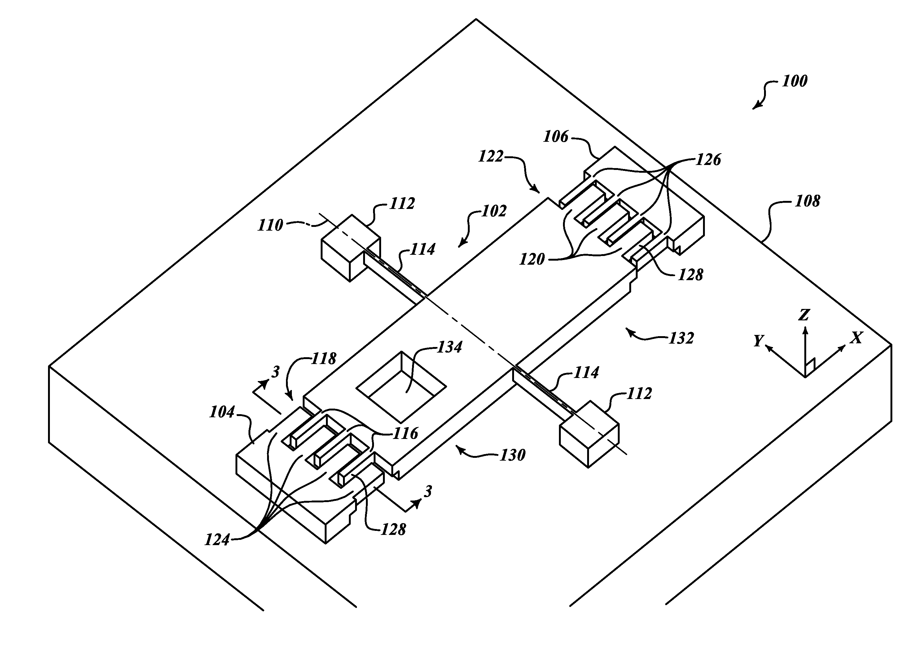
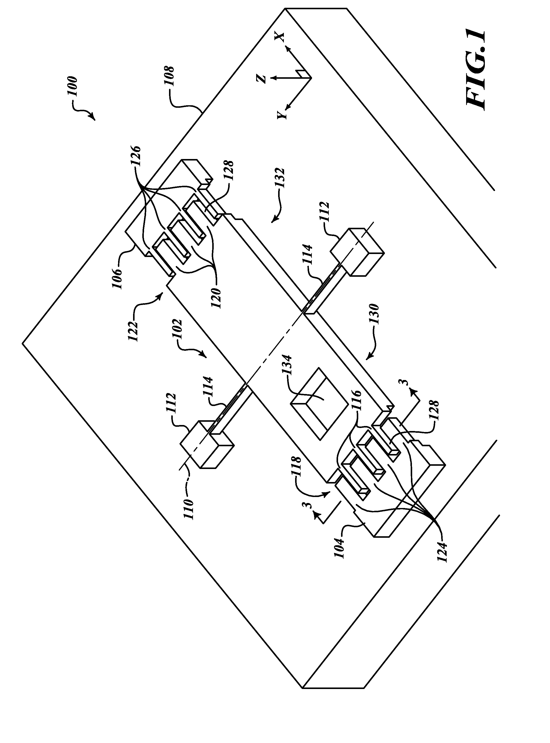
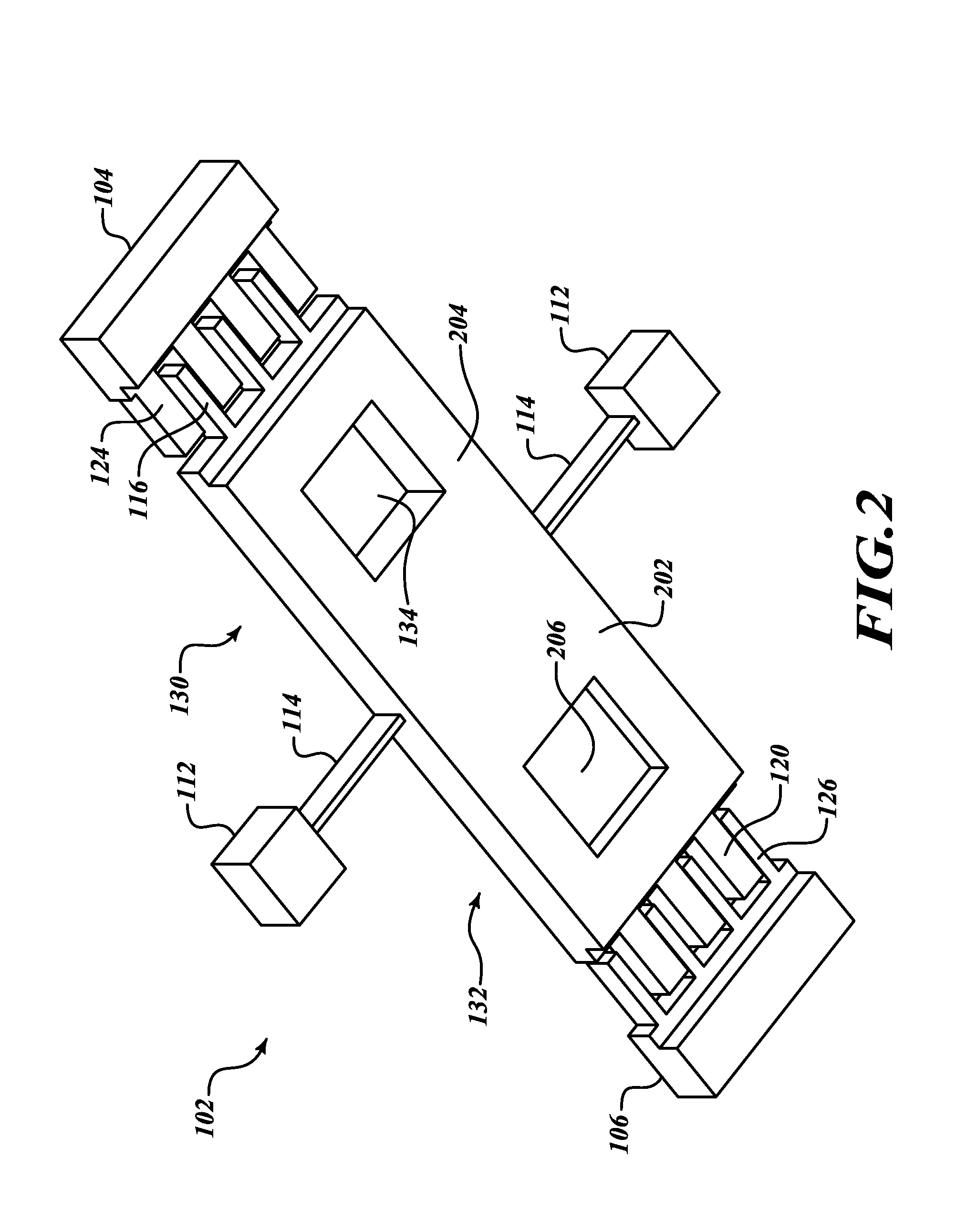
[0012]FIG. 1 is a top side perspective view of a portion of an embodiment of a closed loop linear drive accelerometer 100 that detects out-of-plane linear accelerations. The closed loop linear drive accelerometer 100 includes a proof mass 102, a first stator 104, a second rotor stator 106, and a portion of a substrate 108. Embodiments are fabricated using Micro-Electro-Mechanical Systems (MEMS) technologies.

[0013]An out-of-plane linear acceleration along the Z-axis will cause the pendulous proof mass 102 to rotate. The closed loop mode of operation maintains the position of the proof mass 102 in a substantially fixed position when the closed loop linear drive accelerometer 100 is subjected to the out-of-plane acceleration. That is, voltages are generated and applied to the stators 104 and 106 in an exemplary embodiment to counteract torsional forces caused by the linear acceleration

[0014]The proof mass 102 is suspended above the substrate 108 so that the proof mass 102 may rotate ab...


PUM


Abstract

Systems and methods sense out-of-plane linear accelerations. In an exemplary embodiment, the out-of plane linear accelerometer is accelerated in an out-of-plane direction, wherein the acceleration generates a rotational torque to an unbalanced proof mass. A rebalancing force is applied to at least one plurality of interleaved rotor comb tines and stator comb tines, wherein the rebalancing force opposes the rotational torque, wherein the rotor comb tines are disposed at an end of the unbalanced proof mass, and wherein the stator comb tines are disposed on a stator adjacent to the end of the unbalanced proof mass. An amount of acceleration is then determined based upon the applied rebalancing force.

Description

BACKGROUND OF THE INVENTION[0001]A conventional out-of-plane Micro-Electro-Mechanical Systems (MEMS) device, such as an accelerometer, may include one or more silicon proof masses mechanically coupled to and suspended from a substrate, typically glass, using one or more silicon flexures. A number of recesses etched into the substrate allow selective portions of the MEMS device to move freely within an interior portion of the MEMS device. In certain designs, substrates can be provided above and below the silicon structure to sandwich the proof masses between the two substrates. An out-of-plane MEMS device may be used to determine an out-of-plane linear acceleration by measuring exerted acceleration forces which displace portions of the proof mass.[0002]The movable portion of the proof mass of an accelerometer, referred to herein as a rotor, and an adjacent, fixed portion of the MEMS device, referred to herein as a stator, are separated by a gap. The gap is typically filled with air o...

Claims


Application Information

Patent Timeline
IPC IPC(8): G01P15/10G01P15/125
CPCG01P15/125G01P2015/0882G01P2015/0831G01P15/131G01P2015/0834
Inventor FOSTER, MICHAEL J.
Owner HONEYWELL INT INC
Features
  • Generate Ideas
  • Intellectual Property
  • Life Sciences
  • Materials
  • Tech Scout
  • Unparalleled Data Quality
  • Higher Quality Content
  • 60% Fewer Hallucinations
Learn More