Fuel Filter and Filter Cartridge Allowing the Electrostatic Charges to be Drained Off

a technology of electrostatic charges and fuel filters, applied in the field of fuel filters, can solve the problems of significant concentration of electrostatic charges, short circuit between the connector terminals, and solution nevertheless presents a drawback, and achieve the effect of reducing cost and facilitating deformation

Active Publication Date: 2010-02-04
FILTRAUTO
View PDF12 Cites 18 Cited by
  • Summary
  • Abstract
  • Description
  • Claims
  • Application Information

AI Technical Summary

Benefits of technology

[0016]An advantage of the present invention resides in the fact that it allows the electrostatic charges to be dissipated and avoids the formation of electric arcs between the filter and the structure of the vehicle.
[0017]A further advantage resides in the use of an easily-deformable dissipative flexible contact which makes it possible to take up radial and axial play.
[0018]A yet further advantage resides in the fact that the invention makes it possible to produce a simply-designed fuel filter at a reduced cost.
[0019]A yet further advantage also resides in ease of installation and removal of the filter element without the need for any particular electrical expertise.
[0020]A yet further advantage for certain embodiments of the filter element resides in the fact that the latter does not require the addition of any specific part in relation to a conventional filter.
[0021]A further advantage resides in the recyclability of the filter element.

Problems solved by technology

During the circulation of a fluid, and more particularly when a fuel flows in a filter, the friction of the fluid whilst it passes through the filter medium generates losses of electrons which accumulate at the level of the filter element and the filter bowl, causing a significant concentration of electrostatic charges.
This solution nevertheless presents a drawback when the filter body comprises an electrical connector, for example for supplying a fuel pump or other electrical device such a valve, a heater or a sensor.
In fact, as the filter body is conductive, there is a risk of creating a short-circuit between the connector terminals and affecting the efficiency of the electrical device.
Moreover, the use of plastics or loaded polymers is particularly costly.

Method used


Image

  • Fuel Filter and Filter Cartridge Allowing the Electrostatic Charges to be Drained Off
  • Fuel Filter and Filter Cartridge Allowing the Electrostatic Charges to be Drained Off
  • Fuel Filter and Filter Cartridge Allowing the Electrostatic Charges to be Drained Off

Examples


Embodiment Construction

[0028]The technical effect sought by the invention is the dissipation of electrostatic charges. To this end, it is important to specify the terminology used to classify the properties of the materials. Conductive, dissipative, astatic and insulating materials are differentiated. By “insulating” is meant a material which does not conduct current and does not allow the dissipation of electrostatic charges. Such materials have a surface resistivity greater than 1012 Ohms. The “astatic” materials have a surface resistivity comprised between 109 and 1012 Ohms, the “dissipative” materials have a surface resistivity comprised between 105 and 109 Ohms and the “conductive” materials have a surface resistivity less than 105 Ohms. In the present description, the term “dissipative” will be applied both to the conductive and to the dissipative materials and will denote a property allowing electrostatic discharge.

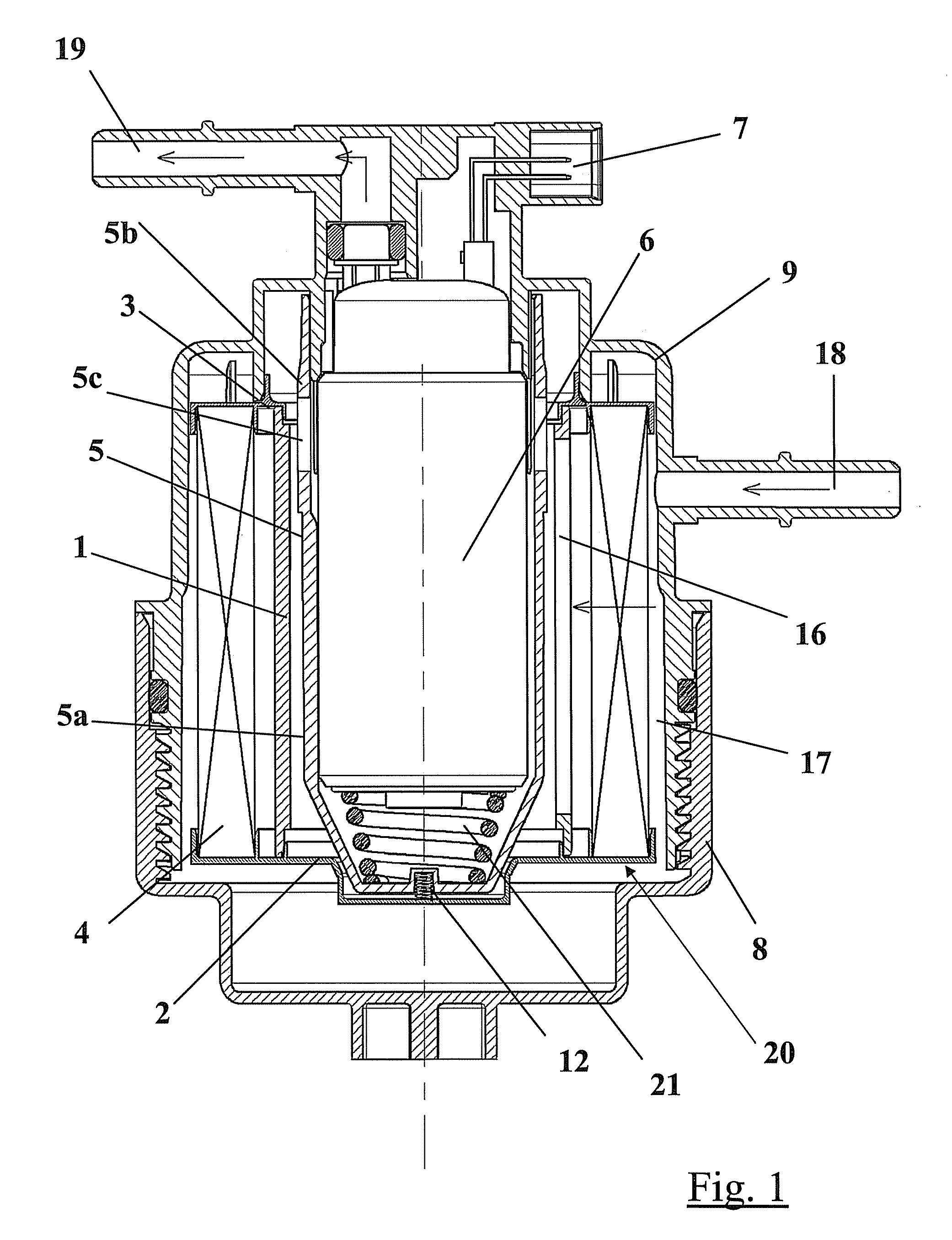
[0029]FIG. 1 is a cross section view showing a fuel filter according to the inventio...


PUM

PropertyMeasurementUnit
flexibleaaaaaaaaaa
dissipative flexibleaaaaaaaaaa
concentrationaaaaaaaaaa

Abstract

A fuel filter comprises a bowl and a cover that form an enclosure, in which a filter element and a electrical device are concentrically arranged, a connector making it possible to connect the device to an external supply is carried by the bowl or by the cover. The electrical device is arranged in a dissipative shell and connected to the earth of the electrical device or of the connector. At least one part of the filter element is dissipative and at least one dissipative flexible contact is arranged between said dissipative part and the shell in order to provide a dissipative continuity between the filter element and the shell.

Description

FIELD OF THE INVENTION[0001]The technical field of the present invention is that of fuel filters and more particularly, fuel filters in which at least one electrical device is integrated.BACKGROUND OF THE INVENTION[0002]During the circulation of a fluid, and more particularly when a fuel flows in a filter, the friction of the fluid whilst it passes through the filter medium generates losses of electrons which accumulate at the level of the filter element and the filter bowl, causing a significant concentration of electrostatic charges. It is thus essential to provide a dissipative path allowing these charges to be dissipated in order to avoid electric arcs being created between the filter and the structure of the vehicle (earth) which could result in a perforation of the filter housing and thus fuel leakages.[0003]A first solution, disclosed by U.S. Pat. No. 6,168,713 consists of producing the filter body from conductive or dissipative material (for example metal or plastic loaded w...

Claims


Application Information

Patent Timeline
Patent Type & Authority Applications(United States)
IPC IPC(8): F02M37/22
CPCB01D2201/50B01D35/26
Inventor BERLAND, YANNFREMONT, LAURENTGIRAULT, EMMANUELPETITEAUX, MATHIEWFAYOLLE, LAURENT
Owner FILTRAUTO
Why Eureka
Try Eureka