Balun signal transformer and method of forming

a signal transformer and transformer technology, applied in the field of balun, can solve problems such as yield loss

Active Publication Date: 2010-02-04
NXP USA INC
View PDF5 Cites 22 Cited by
  • Summary
  • Abstract
  • Description
  • Claims
  • Application Information

AI Technical Summary

Problems solved by technology

In manufacturing, process variations occur that may

Method used


Image

  • Balun signal transformer and method of forming
  • Balun signal transformer and method of forming
  • Balun signal transformer and method of forming

Examples


Embodiment Construction

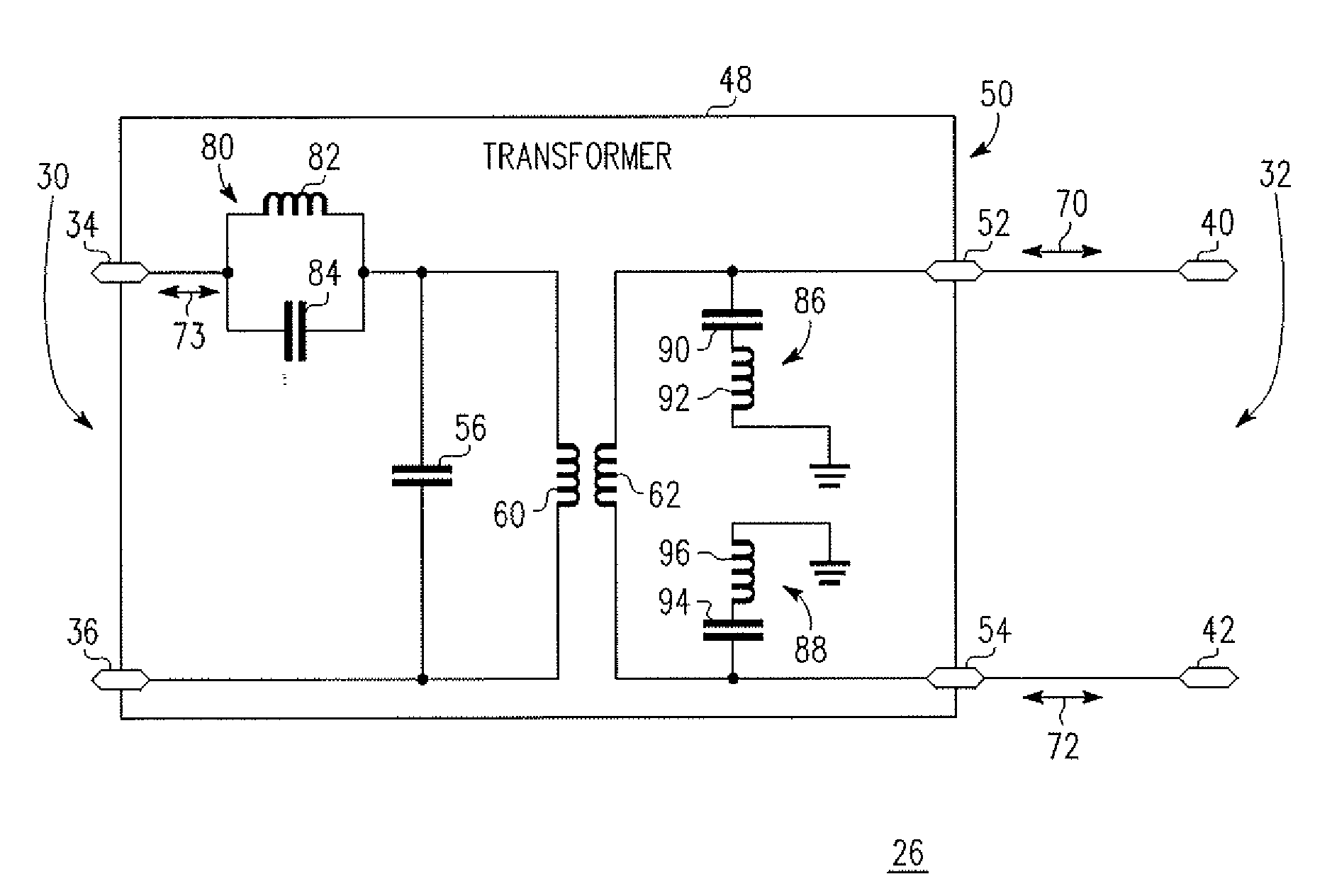
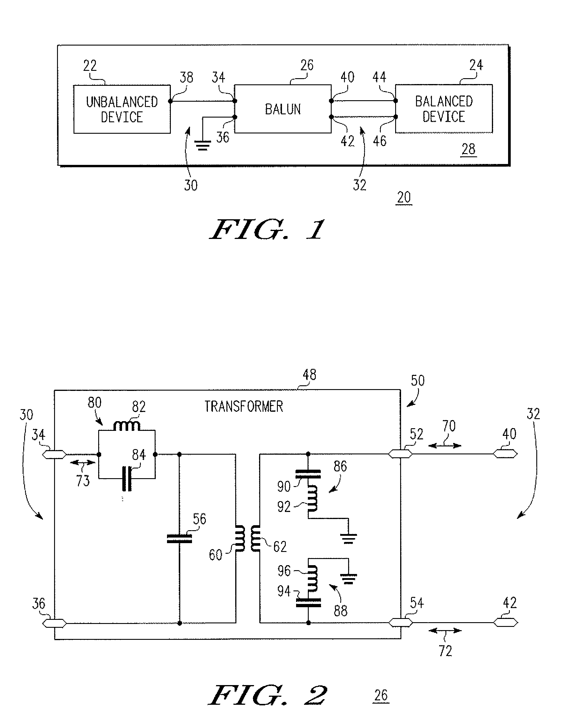
[0011]A system for transforming signals includes a balun (balanced-to-unbalanced) signal transformer interposed between an unbalanced device and a balanced device. The balun signal transformer includes a transformer, which may be symmetric, having a balanced port and an unbalanced port. In one embodiment, two tuned circuits are coupled to the balanced port. The tuned circuits combined with the transformer produce offset resonance, which results in a wider band width for second harmonic suppression. Thus, the process variation tolerance is improved, especially with respect to capacitor variation tolerance of the manufacturing process. As a result, yield and circuit performance are not diminished and may be improved.

[0012]FIG. 1 shows a block diagram of a system 20 for transforming a signal in accordance with one embodiment of the present invention. System 20 includes an unbalanced device 22, a balanced device 24, and a balun signal transformer 26 interposed between unbalanced device ...


PUM


Abstract

A balanced-unbalanced (balun) signal transformer includes an unbalanced port, a balanced port coupled to the unbalanced port, the balanced port comprising a first terminal and a second terminal, a first capacitor coupled to the first terminal, a first inductor coupled to ground and the first capacitor, a second capacitor coupled to the second terminal, and a second inductor coupled to ground and the second capacitor. The transformer may also include a third capacitor coupled to a terminal of the unbalanced port; and a third inductor coupled to the third capacitor and the third terminal.

Description

BACKGROUND [0001]1. Field[0002]The present invention relates generally to balun signal transformers. More specifically, the present invention relates to balun signal transformers that have high second harmonic rejection.[0003]2. Related Art[0004]A balun (balanced-to-unbalanced) signal transformer is a passive electronic circuit that functions to convert an unbalanced signal (i.e., unbalanced in relation to ground) into balanced signals (i.e., balanced in relation to ground) and vice versa of converting balanced signals into an unbalanced signal. A signal incoming to an unbalanced port of the balun transformer may be divided between two balanced ports of the balun transformer providing signals which have the same amplitude but phases differing by one hundred and eighty degrees in relation to one another. For example, baluns may be used in transmitting circuits and receiving circuits of wireless or cable communications systems and for construction of balanced amplifiers, mixers, volta...

Claims


Application Information

Patent Timeline
IPC IPC(8): H03H7/42
CPCH01F19/08H01F2017/0046H03H7/1775H03H7/1758H03H7/1766H03H7/42
Inventor LIU, LIANJUNABROKWAH, JONATHAN K.HARTIN, OLIN L.LI, QIANG
Owner NXP USA INC
Why Eureka
Try Eureka