Utility Metering System With Compact And Robust Antenna For Subsurface Installation

a subsurface installation and metering system technology, applied in the field of utility meters, can solve the problem of more difficult to make the antenna a small componen

Inactive Publication Date: 2010-02-04
BADGER METER
View PDF19 Cites 26 Cited by
  • Summary
  • Abstract
  • Description
  • Claims
  • Application Information

AI Technical Summary

Benefits of technology

[0009]The antenna can be disposed with a transmitter in a tube of less than one

Problems solved by technology

In this range of operation, it is more difficult to make the anten

Method used


Image

  • Utility Metering System With Compact And Robust Antenna For Subsurface Installation
  • Utility Metering System With Compact And Robust Antenna For Subsurface Installation
  • Utility Metering System With Compact And Robust Antenna For Subsurface Installation

Examples


Embodiment Construction

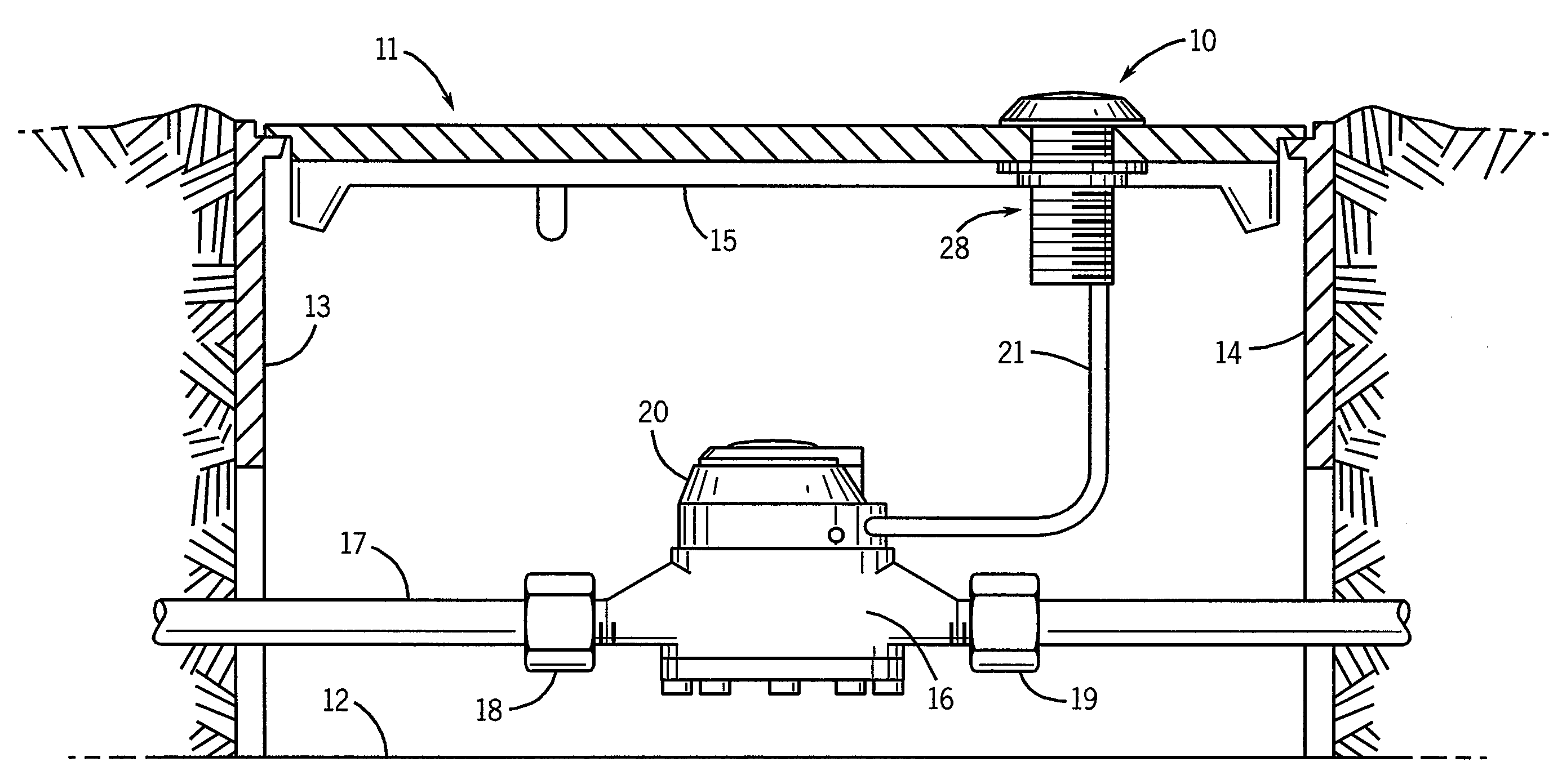
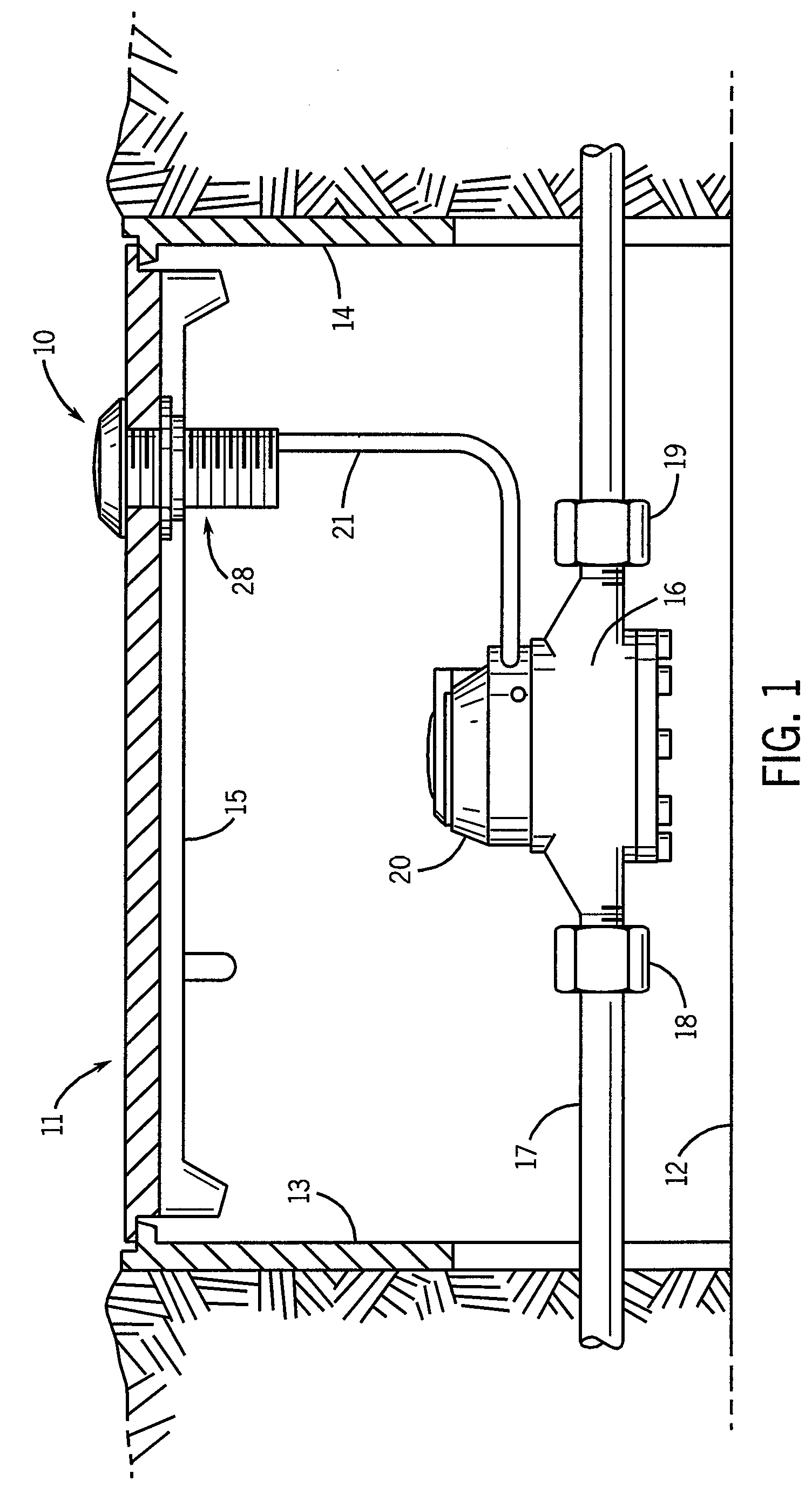
[0018]Referring to FIG. 1, the invention is provided for a pit transmitter assembly 10 to be used in a subsurface pit enclosure 11. The pit is typically made of metal, concrete or other materials and includes sidewalls 13, 14 and a lid 15 which is removable to open the enclosure 11 for access. A bottom wall 12 is optional. The pit enclosure 11 is located along the route of water supply pipe 17. A water meter housing 16 is connected in the water supply line 17, using hex-head nuts 18, 19 which are sealed in a conventional manner against leaks at the connecting points. A water meter register unit 20 is mounted on top of the water meter housing 16. As known in the art, meter registers convert mechanical movements of a meter to visual and numerical representations of consumption often shown in an odometer-type read-out device. The register 20 is preferably a unit that is commercially distributed by Badger Meter, Inc., the assignee of the present invention, under the trade designation “R...


PUM


Abstract

A pit transmitter assembly (10) for RF communication of signals representing utility meter data, includes a transmitter (60) supported by a transmitter substrate (61), a planar ground conductor (43) disposed over the transmitter (60), an antenna substrate (42) disposed on edge on the planar ground conductor (43), a flat coil antenna conductor (41) disposed on two opposite sides of the antenna substrate (42) and in which the transmitter (60) includes an L-C circuit (50) connected to the antenna conductor (41) to provide operation of the antenna in the 450 Mhz-470 Mhz frequency range.

Description

TECHNICAL FIELD[0001]This invention relates to utility meters and in particular to meters located in a pit enclosure in the ground and having a radio transmitter for transmitting metering signals to a receiver in a stationary, non-mobile networks.DESCRIPTION OF THE BACKGROUND ART[0002]In moderate climate zones, utility meters are located in subsurface enclosures in areas adjacent to residences or other dwellings. Such enclosures are referred to as “pits” or “pit boxes.” An example of such enclosure is illustrated in Cerny et al., U.S. Pat. No. 5,298,894, in which a utility meter transmitter is disposed in a pit and includes an antenna projecting above the lid to transmit RF signals to an RF interrogator unit. The transmitter antenna may be installed in pits which are made in whole or in part of cast iron, plastic, or concrete. The lids of these boxes are generally flush with ground level.[0003]The amount of radio frequency energy actually radiated into the airwaves is a function of ...

Claims


Application Information

Patent Timeline
IPC IPC(8): G08C17/02
CPCG01D4/002G01F15/063Y04S20/32H01Q7/00Y02B90/241H01Q1/2233Y02B90/20Y04S20/30
Inventor LAZAR, MARKSCHULTZ, RANDYWEBB, DENNISIZICOVICH, SHLOMOLOCKER, YARUMSHARABI, EREZ
Owner BADGER METER
Why Eureka
Try Eureka