Optically transmissive substrates and light emitting assemblies and methods of making same, and methods of displaying images using the optically transmissive substrates and light emitting assemblies

a technology of optical transmission and light-emitting assemblies, which is applied in the direction of lighting and heating apparatus, instruments, process and machine control, etc., can solve the problems of substantial discontinuities in the shape of optical elements along the edges and hence the pattern

Inactive Publication Date: 2010-02-04
RAMBUS DELAWARE
View PDF100 Cites 60 Cited by
  • Summary
  • Abstract
  • Description
  • Claims
  • Application Information

AI Technical Summary

Benefits of technology

[0006]In accordance with one aspect of the invention, any discontinuities in a larger substantially random pattern of overlapping, intersecting or interlocking optical element shapes may be minimized by making a master having a pattern of overlapping, intersecting or interlocking optical element shapes that are substantially random except along at least one edge

Problems solved by technology

However, when the overlapping optical element shapes in the master are substantially random, the edges of the copies that are made from the master w

Method used


Image

  • Optically transmissive substrates and light emitting assemblies and methods of making same, and methods of displaying images using the optically transmissive substrates and light emitting assemblies
  • Optically transmissive substrates and light emitting assemblies and methods of making same, and methods of displaying images using the optically transmissive substrates and light emitting assemblies
  • Optically transmissive substrates and light emitting assemblies and methods of making same, and methods of displaying images using the optically transmissive substrates and light emitting assemblies

Examples


Embodiment Construction

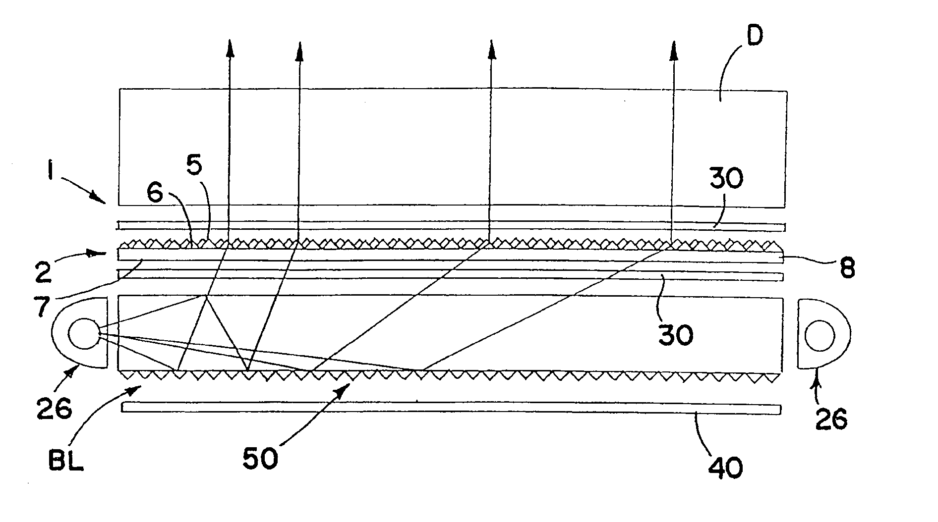
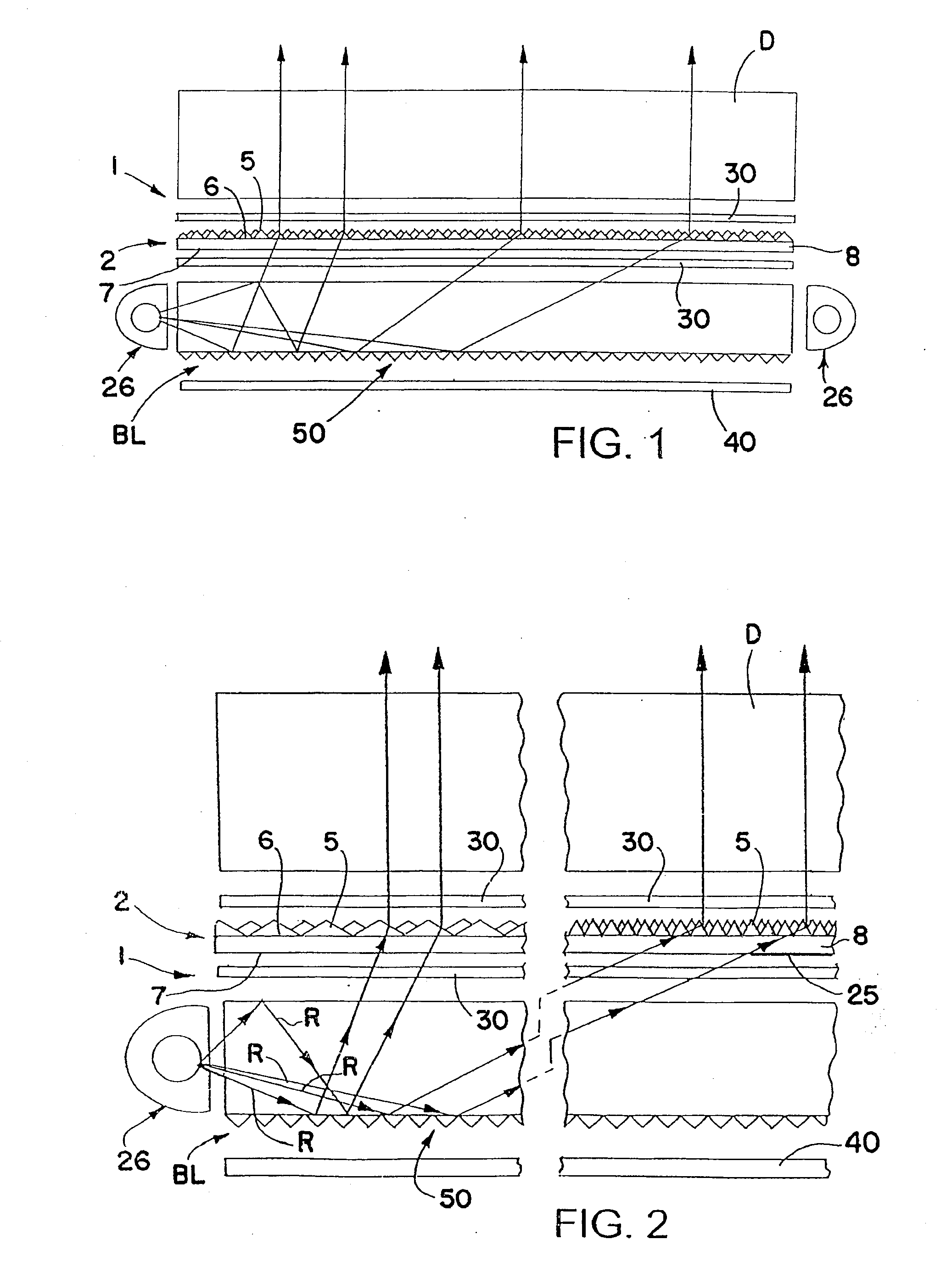
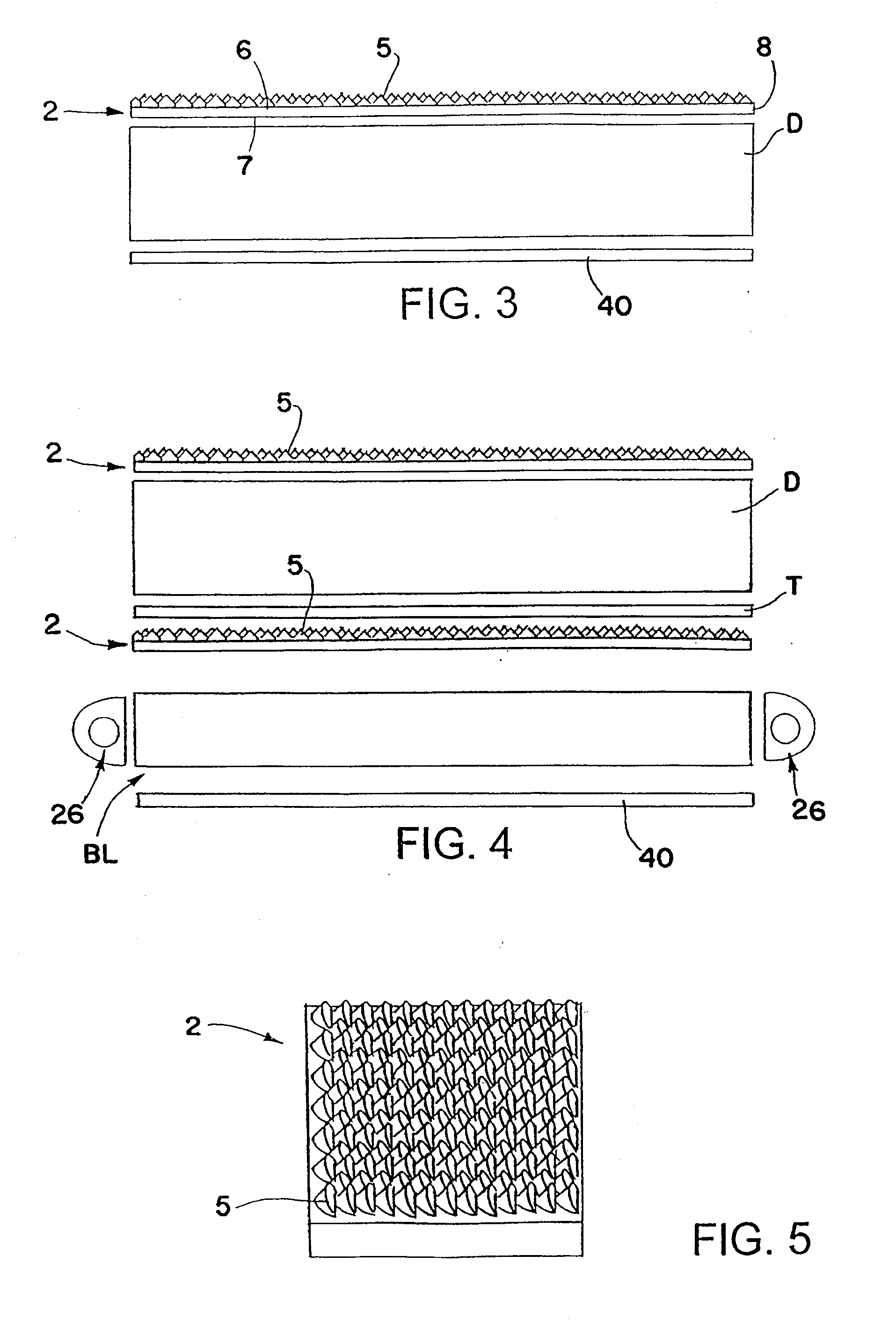
[0079]FIGS. 1 and 2 schematically show one form of backlight system 1 in accordance with this invention including an optically transmissive substrate (including film, sheet, or plate) 2 that redistributes more of the light emitted by a backlight light guide BL or other light source toward a direction more normal to the surface of the substrate. Optically transmissive substrate 2 may be used to redistribute light within a desired viewing angle from almost any light source for lighting, for example, a display D such as a liquid crystal display, used in laptop computers, word processors, avionic displays, cell phones, PDAs and the like, to make the displays brighter. The liquid crystal display can be any type including a transmissive liquid crystal display as schematically shown in FIGS. 1 and 2, a reflective liquid crystal display as schematically shown in FIG. 3 and a transflective liquid crystal display as schematically shown in FIG. 4.

[0080]The reflective liquid crystal display D s...


PUM


Abstract

Images are displayed in response to a video signal using a light emitting assembly having one or more optically transmissive substrates, films or sheets, each having at least one pattern of optical elements on or in the substrates, films or sheets. A plurality of light sources are configured to illuminate one or more output areas of one or more of the substrates, films or sheets. The light emitting assembly is configured to emit light through the pattern of optical elements and produce a predetermined luminance profile of the light emitting assembly. At least one of the light sources is dimmed or boosted in response to an input video signal while operating a liquid crystal display as a light valve to illuminate the liquid crystal display by the light emitting assembly. At least some adjacent substrates, films or sheets may have portions that overlap, and at least one pattern of optical elements on or in at least one side of the substrates, films or sheets may be configured so that discontinuities between the adjacent substrates, films or sheets are minimized. A predetermined light output from the light emitting assembly may be produced by varying the electrical input to at least some of the light sources.

Description

CROSS-REFERENCE TO RELATED APPLICATIONS[0001]This application claims the benefit of U.S. Provisional Application No. 61 / 085,193, filed Jul. 31, 2008, the entire disclosure of which is incorporated herein by reference.FIELD OF THE INVENTION[0002]This invention relates to various methods of making substantially random larger patterns of overlapping, intersecting or interlocking optical element shapes for use in forming patterns of optical elements on or in optically transmissive substrates. Furthermore, this invention relates to the fabrication of optically transmissive substrates and light emitting assemblies having the pattern of optical elements. Yet furthermore, this invention relates to displaying video of improved image quality by using the optically transmissive substrates and light emitting assemblies.BACKGROUND OF THE INVENTION[0003]It is generally known to provide individual optical elements on or in one or more surfaces of optically transmissive substrates including films, ...

Claims


Application Information

Patent Timeline
IPC IPC(8): G09G5/02G09F13/04H05B37/02F21Y101/00
CPCG02B6/0046G02B6/0065G02B6/0073G02F1/133615G02B6/005G09G2310/0235G09G2320/0238G09G2320/0646G09G2330/021G09G3/3406G02F1/133G02F1/1333G02F1/1335G09G3/36
Inventor PARKER, JEFFERY R.MCCOLLUM, TIMOTHY A.HIDE, FUMITOMO
Owner RAMBUS DELAWARE
Why Eureka
Try Eureka