Mixed reality presentation system

a technology of mixed reality and presentation system, which is applied in the field of composition technique of physical space image and virtual space image, can solve the problems of affecting the sense of reality, requiring a lot of time for the generation of cg image, and dynamic registration error between these images

Active Publication Date: 2010-02-04
CANON KK
View PDF4 Cites 92 Cited by
  • Summary
  • Abstract
  • Description
  • Claims
  • Application Information

AI Technical Summary

Benefits of technology

[0011]According to the second aspect of the present invention, a mixed reality presentation system including: a head mounted display having an imaging unit which senses an image of a physical space, and a display unit which displays an image; and an image processing apparatus which generates an image to be displayed on the display unit, wherein the head mounted display comprises: a composition unit which generates a composition image by compositing a physical space image sensed by the imaging unit and a virtual space image transmitted from the image processing apparatus; a unit which outputs the composition image to the display unit; a calculation unit which calculates, as difference information, a difference between a count value of the physical space image counted by a counter which increments the count value by 1 every time the imaging unit senses an image, and a count value for the virtual space image transmitted from the image processing apparatus; a correction unit which updates the difference information by correcting the difference information to ½ when a value indicated by the difference information is not less than 1, to −½ when the value is not more than −1, and to 0 when the value is larger than −1 and less than 1; an acquisition unit which acquires position and orientation information from a sensor which measures a position and orientation of a viewpoint at a rate twice a frame rate of the imaging unit, and acquires a coun...

Problems solved by technology

However, the detection of the position and orientation of the viewpoint of the HMD user, and the generation of a CG image require a lot of time.
Therefore, when a CG image is to be composited on a physical space image which requires little processing time, a dynamic registration error ...

Method used


Image

  • Mixed reality presentation system
  • Mixed reality presentation system
  • Mixed reality presentation system

Examples


first embodiment

[0029]An HMD as a head mounted display used in this embodiment will be described first. FIG. 14 is a view showing a state in which an HMD user 2101 wears a video see-through HMD (to be referred to as a VHMD hereinafter) 101. The VHMD 101 incorporates a three-dimensional (3D) position and orientation sensor (not shown) used to measure the position and orientation of the viewpoint of the HMD user 2101. The 3D position and orientation sensor includes a gyro sensor, acceleration sensor, and magnetic sensor. In addition, the VHMD 101 includes an imaging unit for sensing a moving image of a physical space, and a display unit for displaying an image.

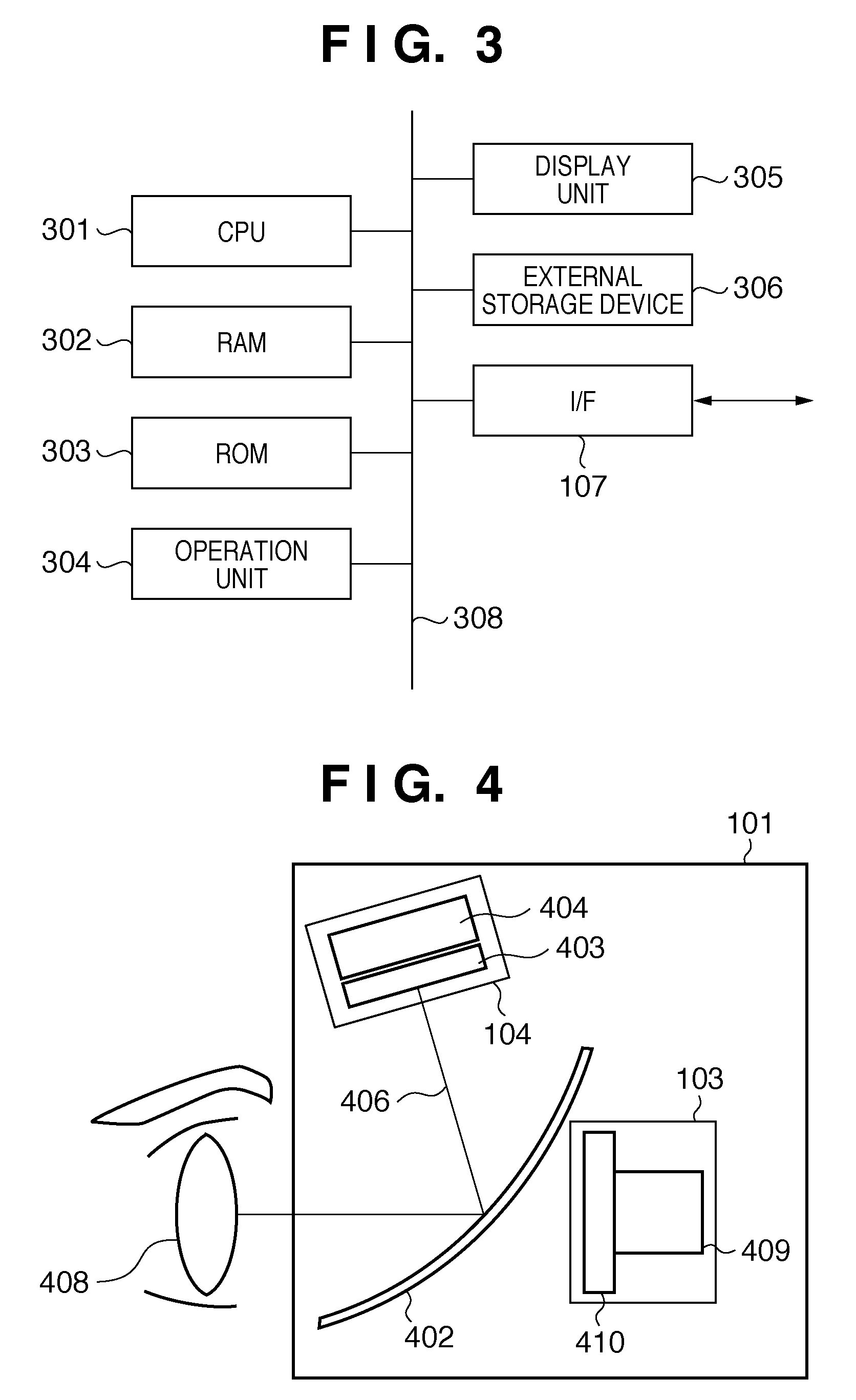
[0030]FIG. 4 is a side sectional view showing an example of the internal arrangement of the VHMD 101.

[0031]Since the VHMD 101 has a symmetric shape, FIG. 4 illustrates the internal arrangement for one eye. Reference numeral 408 denotes an eye of the HMD user 2101. Reference numeral 103 denotes an imaging unit which includes an imaging optical s...

second embodiment

[0079]In the first embodiment, a dynamic registration error between the virtual space image and physical space image is calculated using the imaging time and generation completion predicted time. In this embodiment, this dynamic registration error is calculated using a count value of a counter provided inside the line-of-sight position prediction unit 108. Assume that this counter operates to count at a frequency of 60 Hz as an image frame rate. Also, in this embodiment, assume that the 3D position and orientation sensor 105 operates at a frequency twice the image frame rate, that is, 120 Hz. Of course, the 3D position and orientation sensor 105 acquires position and orientation information for each frame image (in synchronism with an image).

[0080]Note that only differences of this embodiment from the first embodiment will be explained below.

[0081]FIG. 5 is a chart for explaining processing for generating a virtual space image to be composited to a physical space image so as to elim...

third embodiment

[0103]In the first embodiment, the video see-through HMD is used as the head mounted display. In this embodiment, an optical see-through HMD is used as the head mounted display. Only differences of this embodiment from the first embodiment will be described below.

[0104]FIG. 7 is a side sectional view showing an example of the internal arrangement of an optical see-through HMD (OHMD). The same reference numerals in FIG. 7 denote the same parts as in FIG. 4, and a repetitive description thereof will be avoided.

[0105]Reference numeral 702 denotes a half mirror, which mixes a light beam 705 from a physical space and a light beam 406 from a display unit 104, and forms an image on an eye 408 of an HMD user 2101 as a light beam 407 of a composition image.

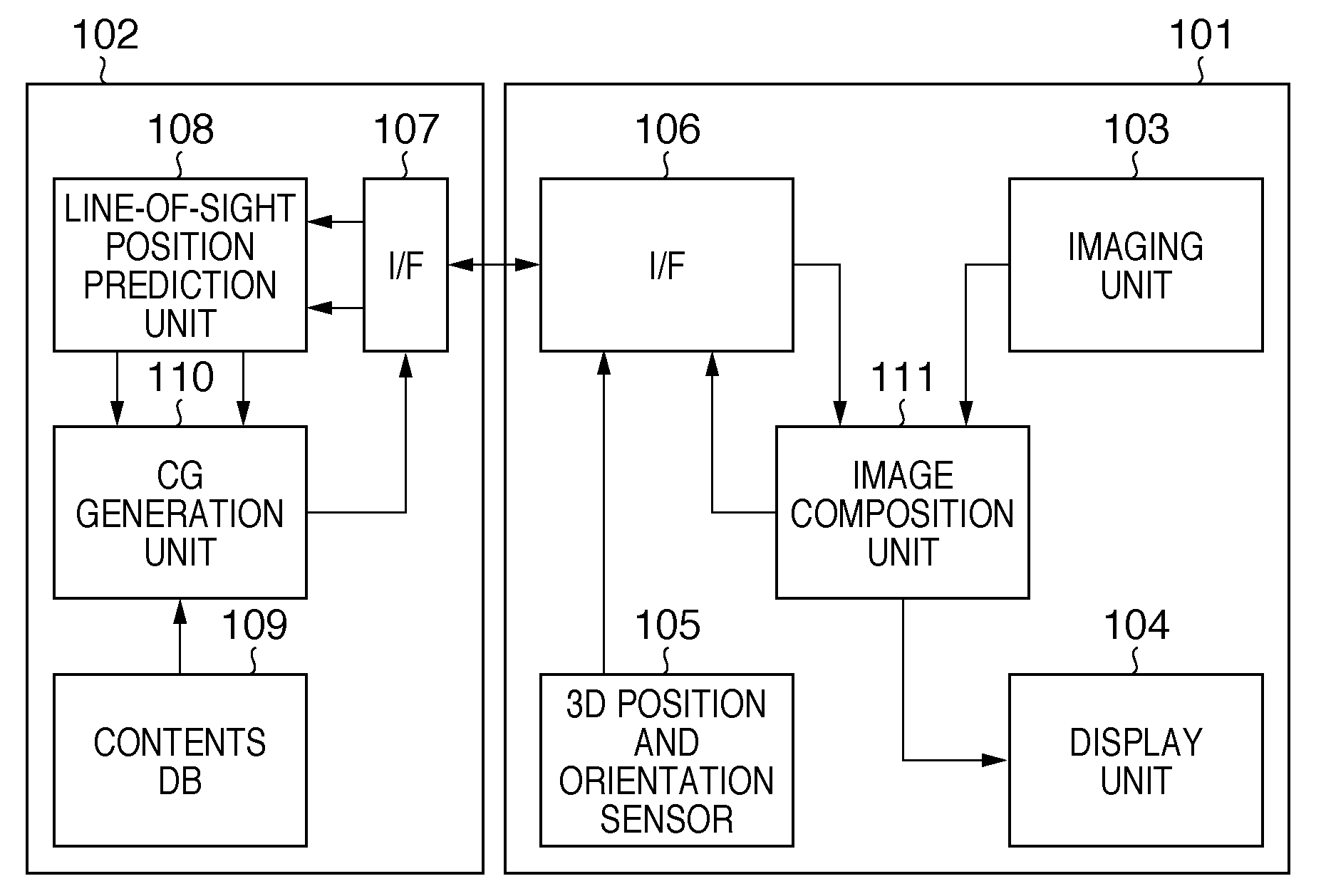
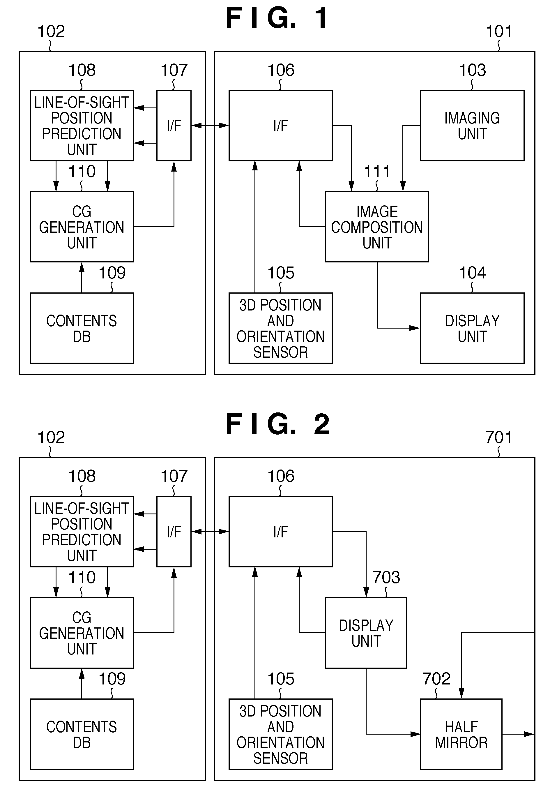
[0106]FIG. 2 is a block diagram showing an example of the functional arrangement of a system according to this embodiment. The same reference numerals in FIG. 2 denote the same parts as in FIG. 1, and a repetitive description thereof will ...


PUM


Abstract

An image composition unit outputs a composition image of a physical space and virtual space to a display unit. The image composition unit calculates, as difference information, a half of the difference between an imaging time of the physical space and a generation completion predicted time of the virtual space. The difference information and acquired position and orientation information are transmitted to an image processing apparatus. A line-of-sight position prediction unit updates previous difference information using the received difference information, calculates, as the generation completion predicted time, a time ahead of a receiving time by the updated difference information, and predicts the position and orientation of a viewpoint at the calculated generation completion predicted time using the received position and orientation information. The virtual space based on the predicted position and orientation, and the generation completion predicted time are transmitted to a VHMD.

Description

BACKGROUND OF THE INVENTION[0001]1. Field of the Invention[0002]The present invention relates to a composition technique of a physical space image and virtual space image.[0003]2. Description of the Related Art[0004]In recent years, as a technique for seamlessly merging a physical world and virtual world in real time, a so-called MR (Mixed Reality) technique is known. As systems that implement the MR technique, two systems have been mainly proposed. One is an MR system using an optical see-through HMD (Head Mounted Display), and the other is an MR system using a video see-through HMD. The system using the optical see-through HMD presents, to the HMD user, an MR image generated by superimposing a CG (Computer Graphics) image onto an image of the physical space observed by the HMD user and formed on the pupils of the user via an optical system. The system using the video see-through HMD presents, to the HMD user, an MR image generated by superimposing a CG image onto an image obtained...

Claims


Application Information

Patent Timeline
IPC IPC(8): G09G5/00
CPCG02B27/017G02B2027/0134G06T19/006G02B2027/0187G02B2027/014
Inventor UTAGAWA, TSUTOMU
Owner CANON KK
Why Eureka
Try Eureka