Optical sheet and method of manufacturing the same

a technology of optical sheets and optical sheets, applied in the field of optical sheets, can solve the problems of increased manufacturing costs, increased assembly properties, and increased manufacturing costs, and achieve the effects of enhanced front luminance and luminance uniformity, enhanced display quality of lcd devices, and enhanced luminance of lcd devices

Active Publication Date: 2010-02-04
TSC OPTOS +1
View PDF10 Cites 44 Cited by
  • Summary
  • Abstract
  • Description
  • Claims
  • Application Information

AI Technical Summary

Benefits of technology

[0022]According to the present invention, front luminance and luminance uniformity may be enhanced due to a juxtaposition of prism patterns and a diffusion portion, and the viewing angle of a liquid crystal display (LCD) device may be enhanced. Thus, the display quality of the LCD device may be enhanced. Moreover, recesses or protrusions which diffuse light rays by using refracting and reflecting characteristics is used in the LCD device without a diffuser diffusing light rays by using dispersion characteristics, so that the luminance of the LCD device may be enhanced.
[0023]In addition, air tunnels are formed within a light control film to enhance the front luminance of the LCD device. Moreover, an upper edge of the prism patterns is not exposed to an outer side thereof, so that scratches may be prevented in another optical sheet. Moreover, the optical sheet includes the diffusion portion or air capsules, so that the luminance uniformity of an LCD device may be enhanced. Moreover, an additional diffusion sheet is omitted, so that an assembly process of the LCD device may be simple and manufacturing costs of the LCD device may be decreased.
[0024]In addition, the optical sheet includes a temporary adhesive layer, so that defects due to external impacts may be easily repaired. Moreover, a temporary adhesive pattern according to the present invention maintains an active combination state, so that resistance to external impacts may be enhanced. Furthermore, the display quality of a display device may be improved through enhanced luminance, a viewing angle, etc., and the thickness of a backlight assembly or the LCD device may be decreased so that the display device may be manufactured in a slim form. Furthermore, the manufacturing process of the optical sheet may be simple, so that the defect rate of the optical sheet may be decreased so that manufacturing costs of the optical sheet may be decreased.

Problems solved by technology

However, since the LCD panel of an LCD device is a non-light-emitting device that is not capable of emitting light on its own, a backlight assembly for supplying light to the LCD panel is required in the LCD device.
However, when the number of the optical sheets is increased, assembly properties may be decreased and manufacturing costs may be increased.
In addition, defects due to scratches may be generated in an area where the optical sheets contact each other.
In addition, the viewing angle of an LCD device may be limited due to the thickness of the liquid crystal layer.

Method used


Image

  • Optical sheet and method of manufacturing the same
  • Optical sheet and method of manufacturing the same
  • Optical sheet and method of manufacturing the same

Examples


example embodiment 1

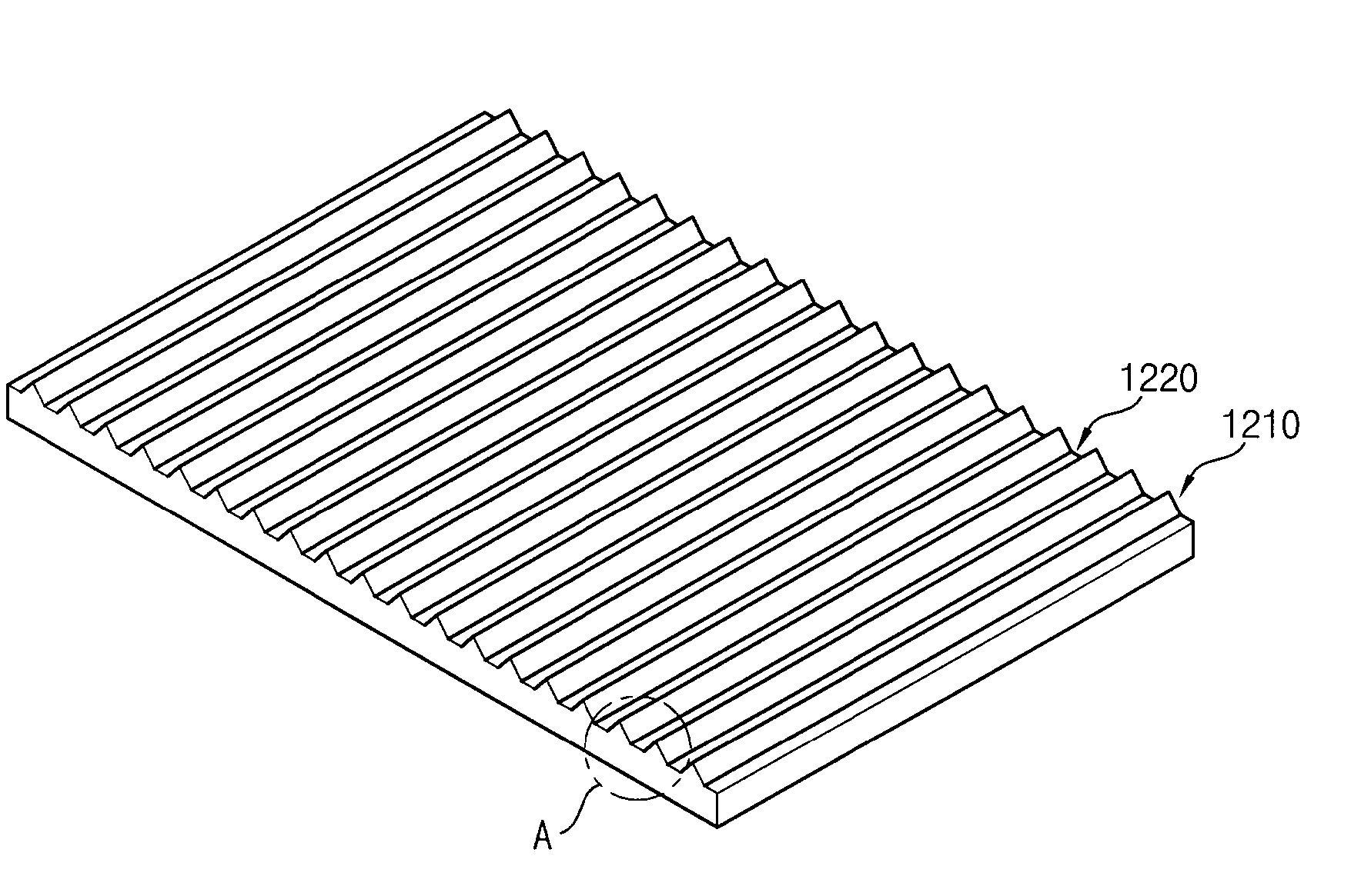
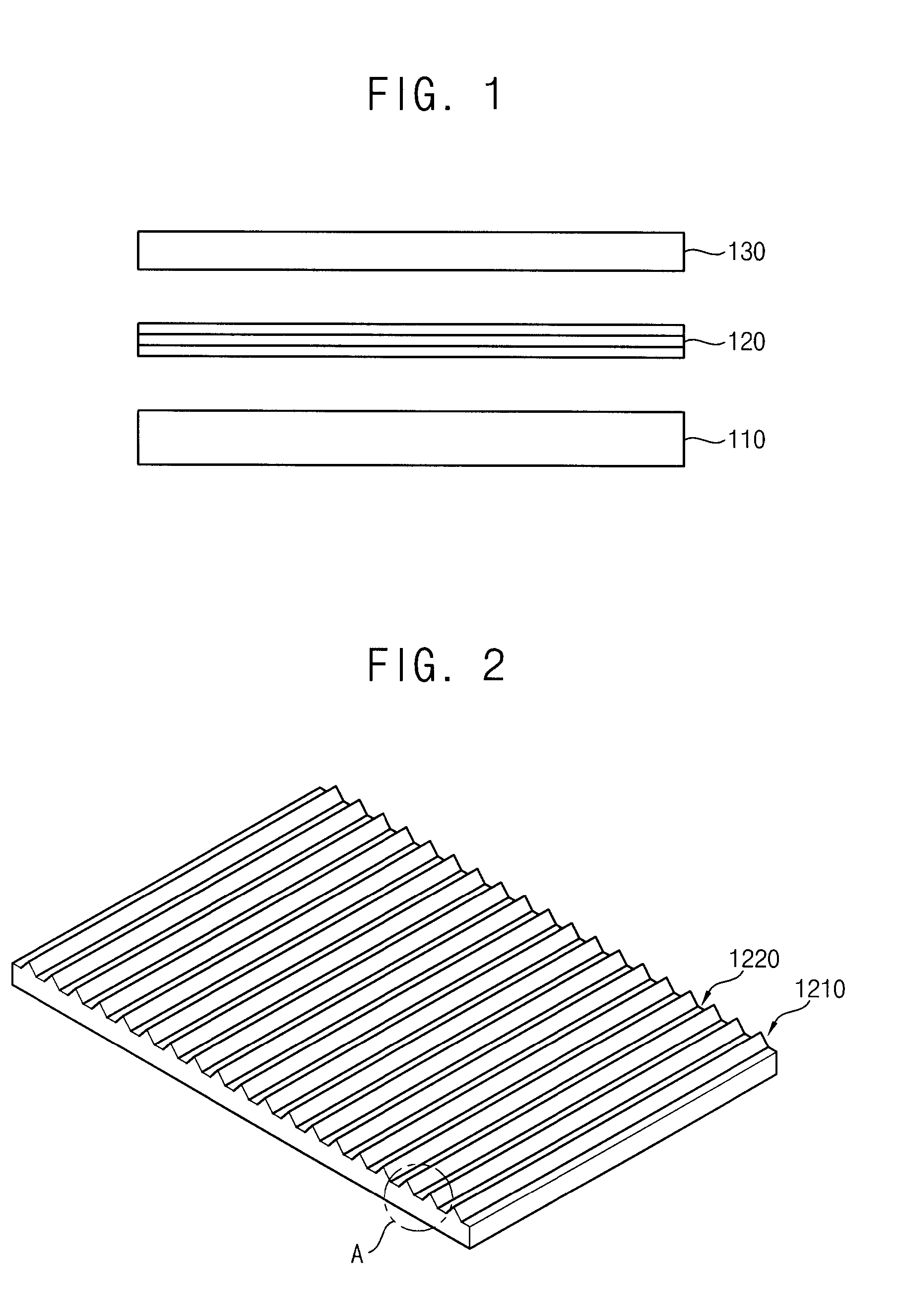
[0118]FIG. 1 is a cross-sectional view illustrating a liquid crystal display (LCD) device according to Example Embodiment 1.

[0119]Referring to FIG. 1, the LCD device includes a light source module 110, an optical sheet 120 and an LCD panel 130.

[0120]The light source module 110 provides light toward the optical sheet 120. The light source module 110 may be classified as either a direct illumination type light source module or an edge illumination type light source module.

[0121]When the light source module 110 is a direct illumination type light source module, a plurality of light sources (not shown) such as a cold cathode fluorescent lamp (CCFL), a flat fluorescent lamp (FFL), a light-emitting diode (LED), etc., may be arranged on a plane.

[0122]When the light source module 110 is an edge illumination type light source module, the light source module 110 may include a light source such as a fluorescent lamp, an LED, etc., and a light guide plate (not shown) guiding light generated by ...

example embodiment 2

[0148]FIG. 5A is a cross-sectional view illustrating an optical sheet according to Example Embodiment 2 of the present invention. FIG. 5B is an image showing the optical sheet of FIG. 5A. In the present embodiment, the optical sheet is substantially the same as the optical sheet of Example Embodiment 1 except for the diffusion member, and thus any further detailed descriptions concerning the same elements will be omitted.

[0149]Referring to FIGS. 5A and 5B, the diffusion member 1230 is disposed between the prism patterns 1210.

[0150]A plurality of protrusion portions 1235 is formed on a diffusion surface of the diffusion member 1230. The protrusion portions 1235 are protruded in a direction identical to a protrusion direction of each of the prism patterns 1210 with respect to the diffusion surface.

[0151]For example, the protrusion portions 1235 may have a hemispherical shape. That is, the prism patterns 1210 have a shape extended in a first direction when viewed from a plan view; howe...

example embodiment 3

[0157]FIG. 6 is a perspective view illustrating an optical sheet according to Example Embodiment 3 of the present invention. FIG. 7A is a cross-sectional view illustrating the optical sheet of FIG. 6. FIG. 7B is an image showing the optical sheet of FIG. 6. In the present embodiment, the optical sheet is substantially the same as the optical sheet of Example Embodiment 1 except for the diffusion member, and thus any further detailed descriptions concerning the same elements will be omitted.

[0158]Referring to FIGS. 6, 7A and 7B, a plurality of recesses 1245 is formed on a diffusion surface of the diffusion member 1240. The recesses 1245 are depressed in a direction opposite to a protrusion direction of each of the prism patterns 1210 with respect to the diffusion surface. In another embodiment, a plurality of protrusion portions (not shown) may be formed to be protruded in a direction identical to a protrusion direction of each of the prism patterns 1210 on the diffusion surface.

[015...


PUM


Abstract

An optical sheet includes a base film in which light is incident from a lower side, a plurality of prism patterns and a diffusion member. The prism patterns are protruded to be spaced apart from each other on the base film to enhance the front luminance of light incident from the lower side of the base film. The diffusion member is disposed between prism patterns to have a diffusion surface in parallel with the base film. The diffusion member includes a plurality of diffusion dots capable of enhancing the luminance uniformity of light incident from the lower side of the base film. Thus, front luminance and luminance uniformity may be enhanced due to a juxtaposition of the prism patterns and the diffusion portion, and the viewing angle of the LCD device may be enhanced.

Description

PRIORITY STATEMENT[0001]This application claims priority under 35 U.S.C. §119 to Korean Patent Application No. 2008-74226, filed on Jul. 29, 2008, No. 2008-74235, filed on Jul. 29, 2008, and No. 2008-101952, filed on Oct. 17, 2008 in the Korean Intellectual Property Office (KIPO), the contents of which are herein incorporated by reference in their entireties.BACKGROUND OF THE INVENTION[0002]1. Field of the Invention[0003]Example embodiments of the present invention relate to an optical sheet and a method of manufacturing the optical sheet. More particularly, example embodiments of the present invention relate to an optical sheet having enhanced optical characteristics and a method of manufacturing the optical sheet.[0004]2. Description of the Related Art[0005]Generally, a liquid crystal display (LCD) panel of an LCD device includes two substrates facing each other, and a liquid crystal layer interposed between the substrates. The LCD panel controls the light transmittance of the liq...

Claims


Application Information

Patent Timeline
Patent Type & Authority Applications(United States)
IPC IPC(8): F21V7/04H01J9/24
CPCF21V5/02G02B5/045G02B5/02
Inventor LEE, DAE-HWANKIM, WOO-TAELEE, KYOUNG-SOOKIM, SUKHWANG, JAE-SUNAN, KWANG-JOONCHUNG, JIN-YONGBYUN, DAL-SEOK
Owner TSC OPTOS
Why Eureka
Try Eureka