Elliptic rubber stopper supply method and elliptic rubber stopper supply device

a technology of elliptic rubber stopper and supply method, which is applied in the direction of chutes, manufacturing tools, transportation and packaging, etc., can solve the problems of blocking the supply route of rubber stopper to an assembling side with a predefined shape, unable to perform smooth supply, and unable to supply elliptic rubber stopper, etc., to achieve smooth and steady supply, prevent the effect of blocking the supply route of rubber stopper

Active Publication Date: 2010-02-04
YAZAKI CORP +1
View PDF2 Cites 2 Cited by
  • Summary
  • Abstract
  • Description
  • Claims
  • Application Information

AI Technical Summary

Benefits of technology

[0029]According to the present invention, by spraying alternately gas from both sides of the rubber stopper on the rubber stopper, clogging the supply route with the rubber stopper can be prevented. Additionally, the rubber stopper can be smoothly and steadily supplied to an assembling side of the rubber stopper. Also, a direction of the rubber stopper is corrected only by gas without using a solid body such as a pin. Thereby, a function as a waterproof rubber stopper can be exerted without damaging a flexible rubber stopper.
[0030]According to the present invention, the rubber stopper can be transferred to the discharge portion without changing circumferential directions of a short diameter of the rubber stopper and of a long diameter thereof from the first hole in the supply route. Further, the rubber stopper can be supplied to next process in the same direction from the discharge portion.
[0031]According to the present invention, in a condition that the circumferential directions of the short diameter and of the long diameter are kept, the short diameter of the rubber stopper and the long diameter thereof can be reversed in an axial direction as necessary in next process, and can supply the rubber stopper to next process from the discharge portion.
[0032]The above and other objects and features of this invention will become more apparent from the following description taken in conjunction with the accompanying drawings.

Problems solved by technology

Furthermore, the rubber stopper can not be supplied to an assembling side with a predefined shape.
For this reason, there is a problem such that the elliptic rubber stopper is blocked with a supply route.
In addition, smooth supply was not performed.

Method used


Image

  • Elliptic rubber stopper supply method and elliptic rubber stopper supply device
  • Elliptic rubber stopper supply method and elliptic rubber stopper supply device
  • Elliptic rubber stopper supply method and elliptic rubber stopper supply device

Examples


Embodiment Construction

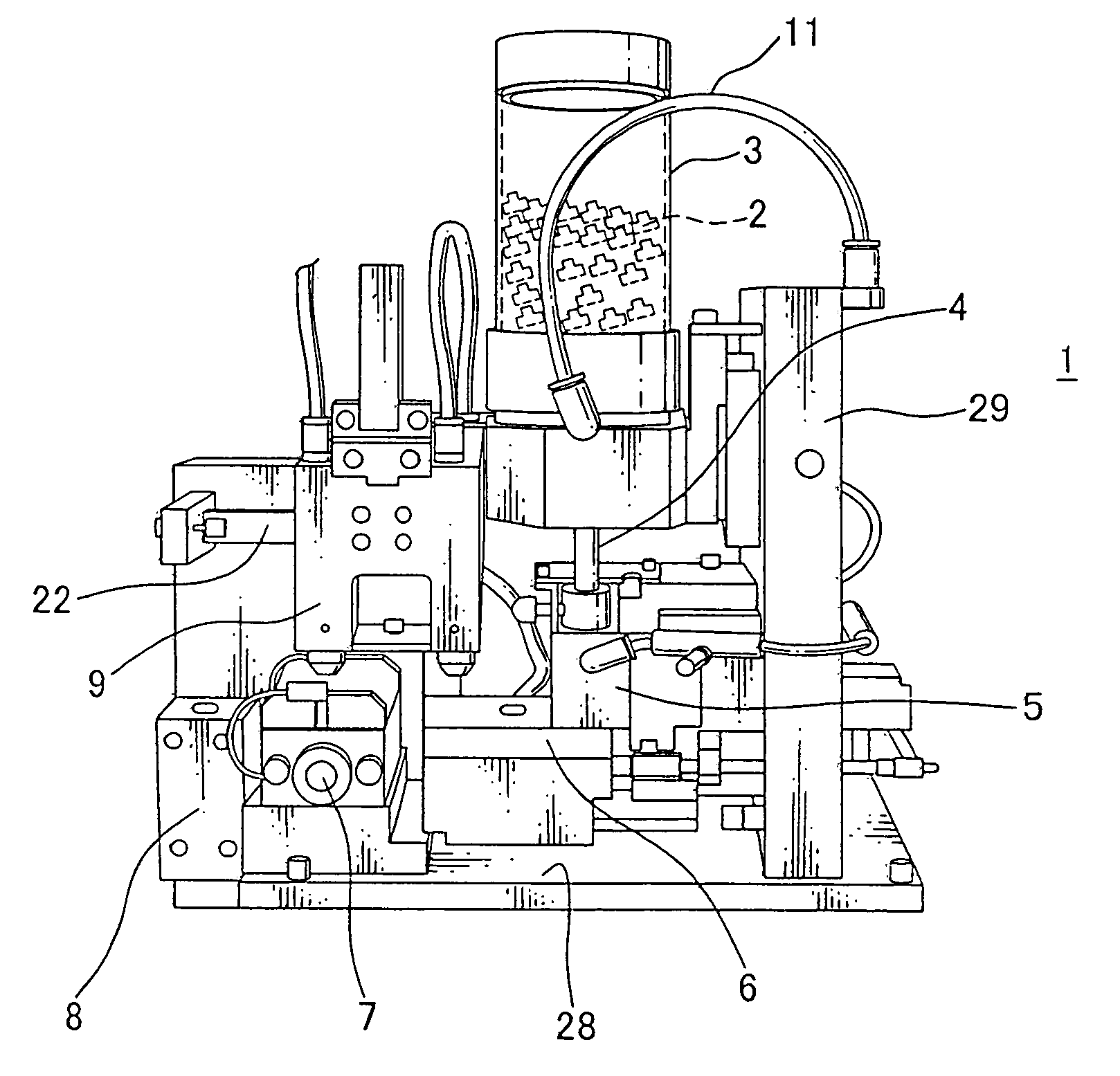
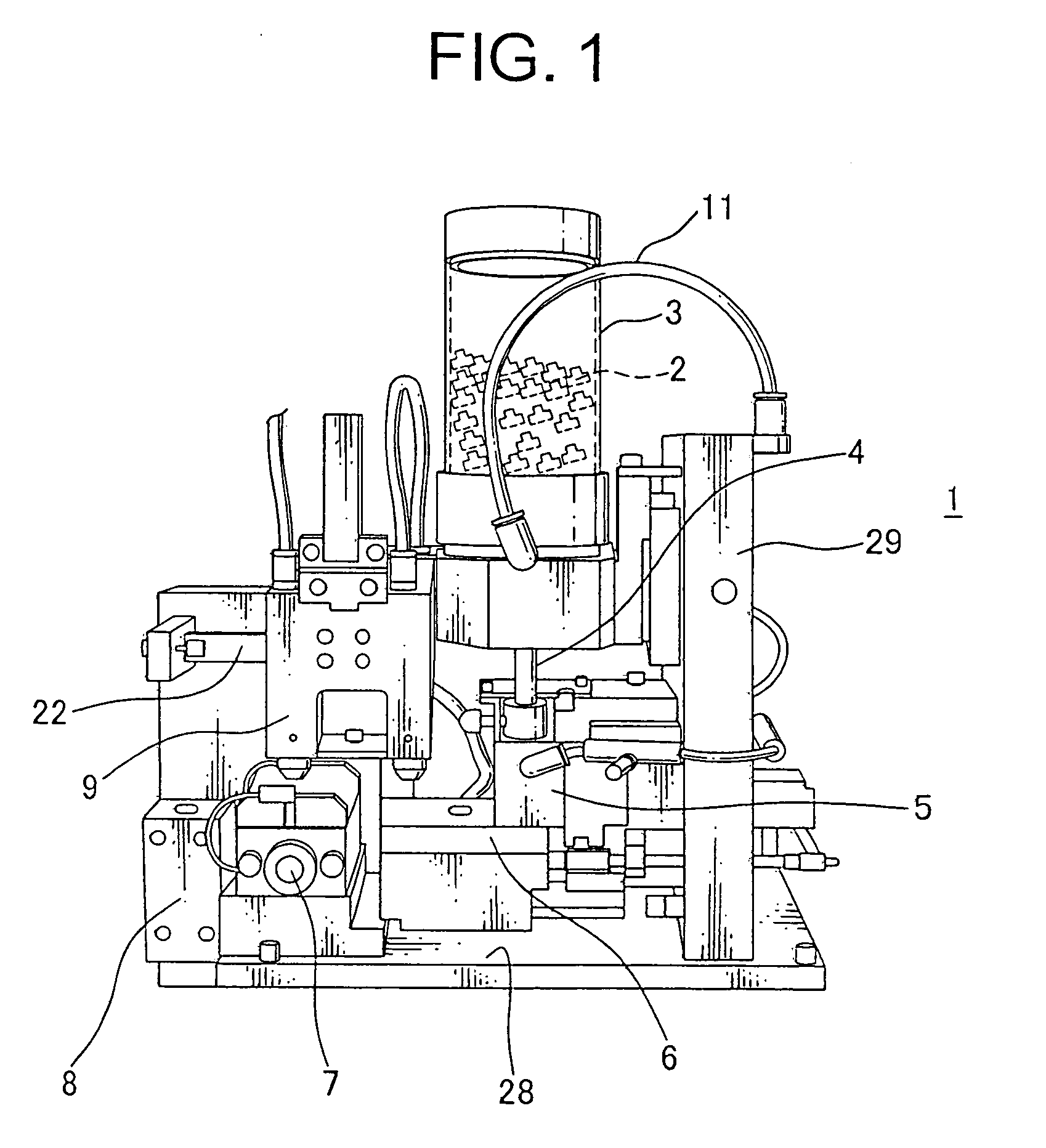
[0055]FIG. 1 shows an embodiment of an elliptic rubber stopper supply device, to which a supply method of the elliptic rubber stopper is applied, of the present invention.

[0056]The elliptic rubber stopper supply device 1 has a hopper 3, a drop pipe 4, a first rubber stopper corrective portion 5, a delivery table 6, an reverse portion 7 (second corrective portion), a discharge portion 8, a transfer portion 9 and a tube 10. The hopper 3 receives a plurality of waterproof rubber stoppers 2, and formed with synthetic resin and metal. The drop pipe 4 is connected to a bottom portion of the hopper 3 and vertically placed with the bottom up. The drop pipe 4 is made of metal. The first rubber stopper corrective portion 5 is connected to a bottom portion of the drop pipe 4. The delivery table 6, the reverse portion 7 (second corrective portion) and the discharge portion 8 are abreast arranged. The rubber stopper 2 is positioned on a lower side of the first rubber stopper corrective portion 5...


PUM


Abstract

The present invention is to provide an elliptic rubber stopper supply method and device thereof, which can smoothly and steadily supply an elliptic rubber stopper to an assembling side of a rubber stopper without blocking a supply route with the rubber stopper. The elliptic rubber stopper supply device sprays alternately a gas on a rubber stopper, matches a minor axial direction of the rubber stopper to a spraying direction of the gas, and inserts the rubber stopper into an elliptic first hole in that condition. Also, the device includes first shape corrective portion for correcting a shape of the rubber stopper. The first shape corrective portion has a rubber stopper receiving portion and a pair of air outlets for spraying alternately a gas on both side surfaces of the rubber stopper. One of the air outlets is arranged on the one side of the rubber stopper receiving portion, the other is arranged on the other side thereof. Each the air outlet is offset in a rubber stopper axial direction and located.

Description

[0001]The priority application Number Japan Patent Application No. 2008-194872 upon which this patent application is based is hereby incorporated by reference.BACKGROUND OF THE INVENTION[0002]1. Filed of the Invention[0003]The present invention relates to an elliptic rubber stopper supply method and device thereof, which corrects a shape (direction) of a rubber stopper at a certain shape and supply. For example, the elliptic rubber stopper supply method and device thereof is performed before a process inserting the electric rubber stopper into an electric wire. The electric rubber stopper prevents water from entering into a terminal receiving chamber of a connector.[0004]2. Description of the Related Art[0005]FIG. 8 shows an embodiment of conventional rubber stopper supply device (patent document 1). The rubber stopper 52 is attached to an insulating coating of an electric wire (not shown), and blocks an entrance of a receiving chamber in a connector housing (not shown). Thereby, th...

Claims


Application Information

Patent Timeline
Patent Type & Authority Applications(United States)
IPC IPC(8): B65G65/30B23Q5/22
CPCB65G47/1457B65G47/525B65G47/244
Inventor NOMOTO, YOSHIAKIISHIGURE, KANJI
Owner YAZAKI CORP
Why Eureka
Try Eureka