Medical Ultrasonic Cauterization and Cutting Device and Method

a cutting device and ultrasonic technology, applied in the field of ultrasonic cutting devices, can solve the problems of not receiving enough movement energy to generate the necessary heat, limiting the speed and size of the waveform used to produce ultrasonic movement, and exceeding the width of the hotspot at the end of prior,

Active Publication Date: 2010-02-04
TYCO HEALTHCARE GRP LP
View PDF12 Cites 176 Cited by
  • Summary
  • Abstract
  • Description
  • Claims
  • Application Information

AI Technical Summary

Problems solved by technology

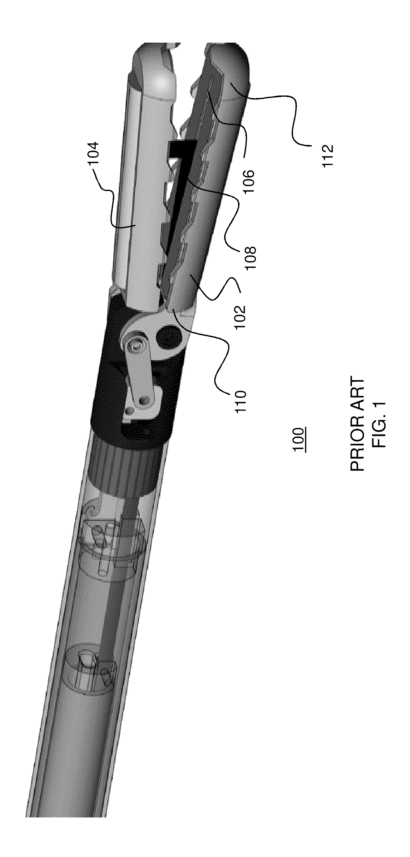
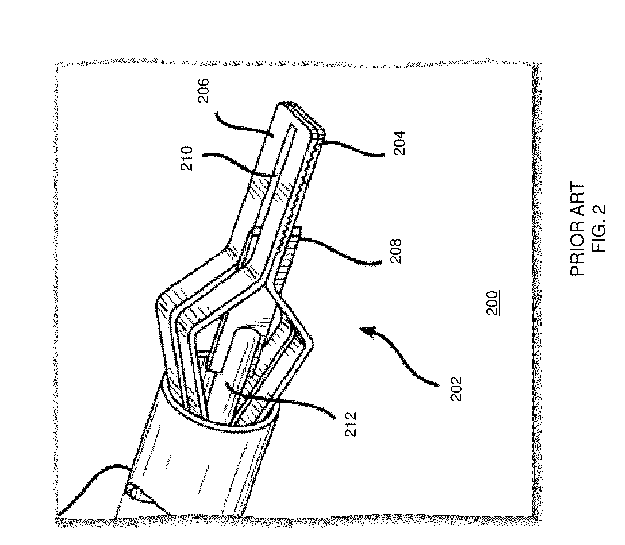
Physical limitations of known materials used for ultrasonic generators and waveguides limit the speed and size of waveforms used to produce the ultrasonic movement.
Tissue touching the waveguide at a particular distance away from the end of the waveguide (outside the hot spot) may be cut, but will not receive enough movement energy to generate the necessary heat to cause hemostasis.
However, larger vessels, such as those with a diameter greater than 7 mm, exceed the width of the hotspot at the end of prior-art blades.
If this device were used on a vessel, it would not provide coaptive forces to opposing walls of the vessel as it translates and cuts.
Naturally, as the diameter of the vessel being cut increases, this hemostasis problem is exacerbated.

Method used


Image

  • Medical Ultrasonic Cauterization and Cutting Device and Method
  • Medical Ultrasonic Cauterization and Cutting Device and Method
  • Medical Ultrasonic Cauterization and Cutting Device and Method

Examples


Embodiment Construction

[0036]While the specification concludes with claims defining the features of the invention that are regarded as novel, it is believed that the invention will be better understood from a consideration of the following description in conjunction with the drawing figures, in which like reference numerals are carried forward. Accordingly, the apparatus components and method steps have been represented where appropriate by conventional symbols in the drawings, showing only those specific details that are pertinent to understanding the embodiments of the present invention so as not to obscure the disclosure with details that will be readily apparent to those of ordinary skill in the art having the benefit of the description herein. Alternate embodiments may be devised without departing from the spirit or the scope of the invention. Additionally, well-known elements of exemplary embodiments of the invention will not be described in detail or will be omitted so as not to obscure the relevan...


PUM


Abstract

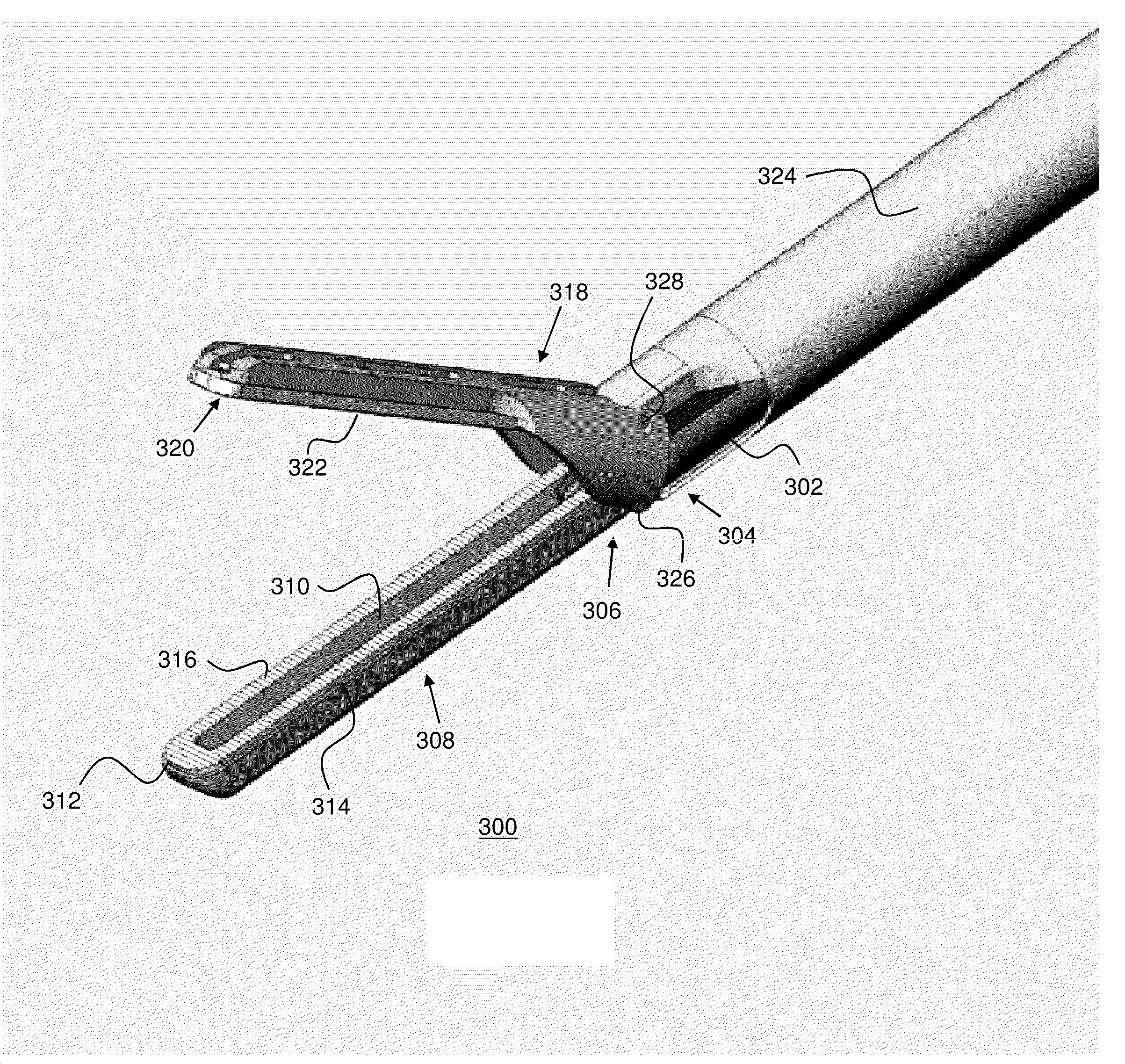
An ultrasonic surgical instrument includes a shaft having a proximal end and a distal end and a first jaw having a proximal end and a distal end, the distal end of the shaft terminating at the proximal end of the first jaw and the first jaw has an internal trough running from and through the proximal end of the first jaw and terminating at a point prior to the distal end of the first jaw and a surface having a plurality of teeth on either side of the trough and at the distal end of the first jaw. A second jaw has a surface facing the surface of the first jaw and having a plurality of teeth thereat. An ultrasonic waveguide extends beyond the shaft and is slidably engagable with the trough, where the ultrasonic waveguide has a distal end, a proximal end, a top surface portion, and a tissue compressing surface upwardly sloping from the distal end of the ultrasonic waveguide to the proximal end of the ultrasonic waveguide, at least one of the tissue compressing surface and the top surface portion forming a cutting surface and wherein the jaws are operable to compress tissue therebetween and the ultrasonic waveguide is operable to slide within the trough to further compress and cut the compressed tissue as the ultrasonic waveguide moves in a direction from the proximal end of the first jaw to the distal end of the first jaw.

Description

BACKGROUND OF THE INVENTION[0001]1. Field of the Invention[0002]The present invention relates generally to an ultrasonic cutting device and, more particularly, relates to a surgical cutting device with vessel-grasping jaws and an extendable blade-shaped ultrasonic cutting and cauterizing waveguide.[0003]2. Description of the Related Art[0004]Ultrasonic instruments are effectively used in the treatment of many medical conditions. Cutting instruments that utilize ultrasonic waves employ an ultrasonic transducer to generate vibrations along a longitudinal axis of a cutting blade. By placing a resonant wave along the length of the blade, high-speed longitudinal mechanical movement is produced at the blade's end. These instruments are advantageous because the mechanical vibrations transmitted to the end of the blade are very effective at cutting organic tissue and, simultaneously, at generating heat sufficient to cauterize the tissue. Such instruments are particularly well suited for use...

Claims


Application Information

Patent Timeline
Patent Type & Authority Applications(United States)
IPC IPC(8): A61B17/32
CPCA61B17/320092A61B17/285A61B2017/320093A61B2017/320094A61B2017/320095
Inventor PALMER, MATTHEW A.DEVILLE, DEREK DEESMITH, KEVIN W.
Owner TYCO HEALTHCARE GRP LP
Why Eureka
Try Eureka