Switch

a technology of switch and contact surface, which is applied in the field of switch, can solve the problems of large solder contact surface area and inability to obtain great solder adhesion strength, and achieve the effects of stable mounting strength, easy centered, and stable operation

Inactive Publication Date: 2010-02-11
SMK CORP
View PDF3 Cites 19 Cited by
  • Summary
  • Abstract
  • Description
  • Claims
  • Application Information

AI Technical Summary

Benefits of technology

[0014]By forming on the housing or cover that configures the switch protruding parts having equal amounts of protrusion, stable mounting strength and stable operation are made p

Problems solved by technology

Nonetheless, in the previously described conventional example, no opening such as a through-hole or a cutaway was formed in the terminals 130, and therefore it was difficult to make a large solder contact surface area for the solder connection of the push button switch to the substrate 170, and great solder adhesion strength could no

Method used


Image

  • Switch
  • Switch
  • Switch

Examples


Embodiment Construction

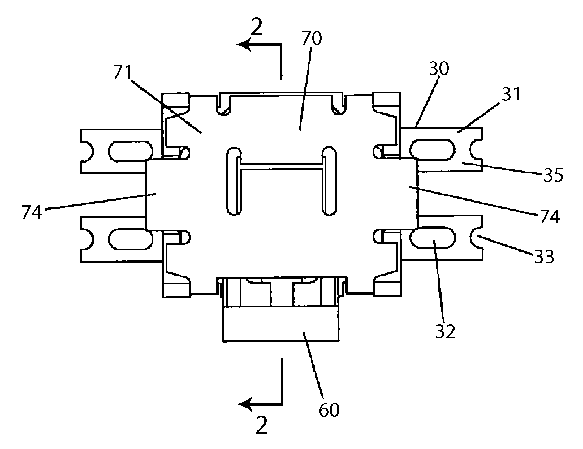
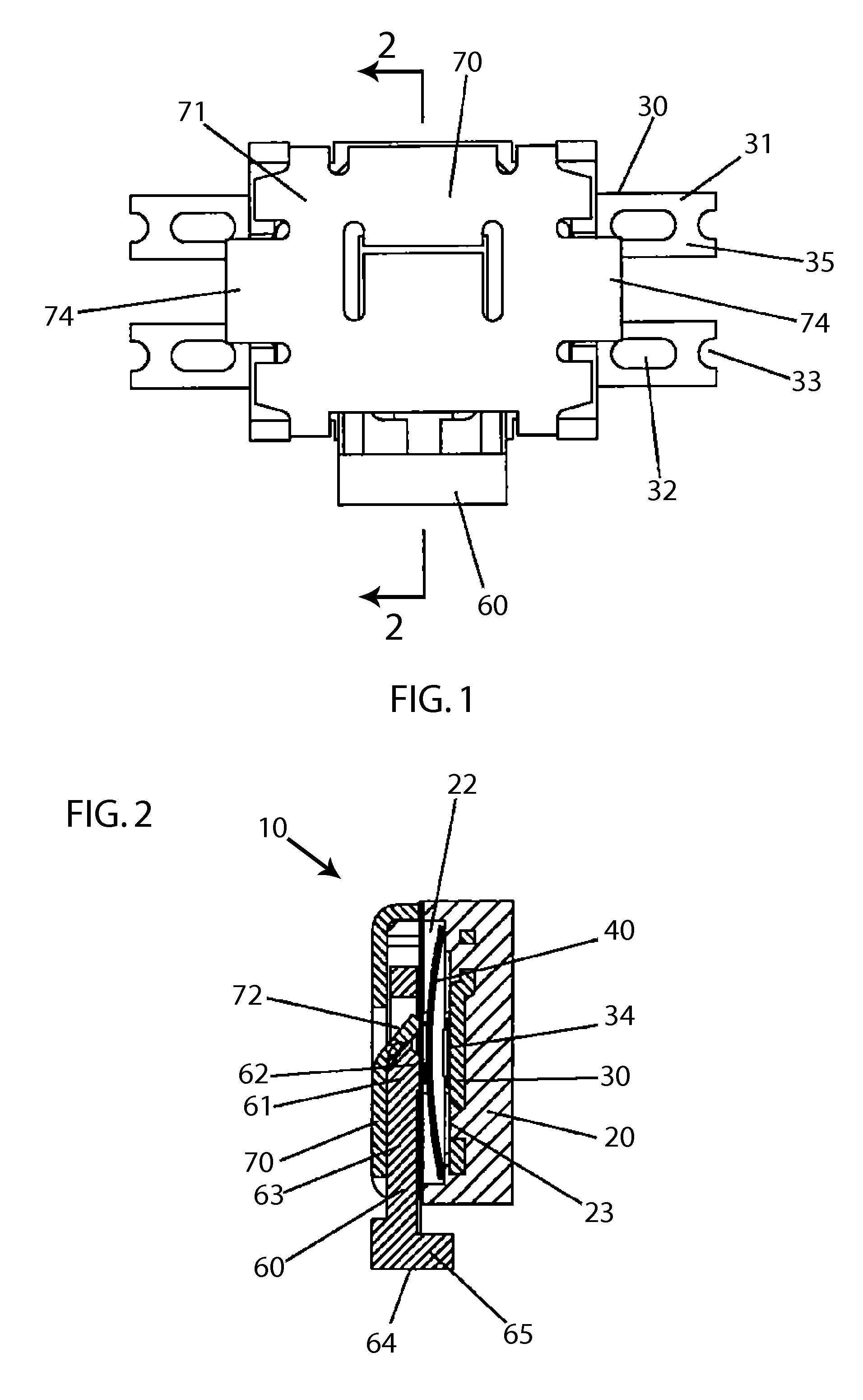
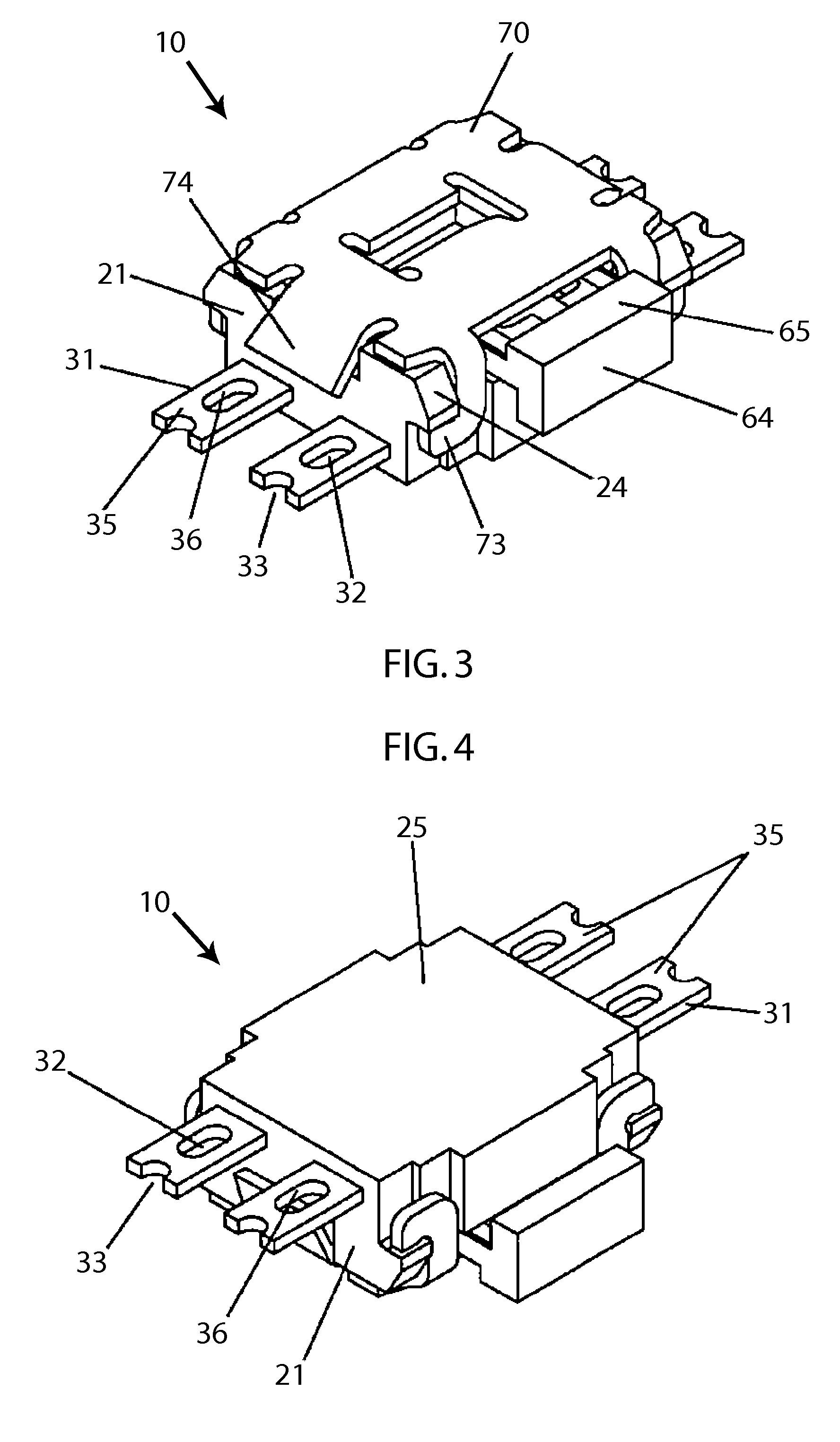
[0028]A listing of some of the reference numerals that are used in the drawings, together with descriptions of the corresponding elements, is provided below.

10Push button switch11Main body20Housing21Housing side surface22Opening23Bottom surface part24Latch convex part25Housing bottom surface26Convex part30Terminal31Solder connection part of32Through-holeterminal33Cutaway part34Contact point35Solder connection surface36Inner surface37End surface40Contact plate50Substrate51Solder mounting surface ofsubstrate (mounting pattern)52Substrate cutaway part53Substrate cutaway end surface60Manipulation member61Tip part62Push part63Push piece64Perpendicular flat surface65Manipulation part70Cover71Top surface part72Guide tongue part73Latch part74Bent part80Solder fillet90Gap91Connected space100Conventional push button101Connection pointswitch110Housing111Housing side surface112Housing bottom surface120Push button130Terminal131Surface with solder132Solder connection part133Output part160Metal co...


PUM


Abstract

A switch having terminals that provide from side surfaces of a switch housing for mounting on a substrate. Through-holes are provided in the terminals. A main body is installed in a cutaway part of the substrate to form a gap between the housing side surface and the cutaway part. When soldering a solder connection surface of the terminal to the solder mounting surface of the substrate, flux flows out to a substrate end surface through a space formed continuously between each through-hole and the gap, such that there is no penetration of flux into the interior of the switch. As a result, contact operation is made stable. In addition, the solder connection strength is also improved by forming a solder fillet on the interior surface of the through-hole.

Description

CROSS-REFERENCE TO RELATED APPLICATIONS[0001]This application claims priority from Japanese Patent Application No. 2008-204393, filed Aug. 7, 2008, which is incorporated by reference herein in its entirety.FIELD OF THE INVENTION[0002]The present invention relates to a switch (for example, a push button switch) mounted on a substrate (for example, a printed circuit substrate) of various types of electronic devices; and more particularly relates to a push button switch mounted in the cutaway part of a substrate.BACKGROUND OF THE INVENTION[0003]As indicated in FIGS. 11 and 12 and described by Japanese Unexamined Patent Application No. 2006-210195, which is incorporated by reference herein in its entirety, in the past a type of push button switch 100 comprised a housing 110, which housed a contact point and was installed on a substrate 170, and a push button 120, which protruded from one side surface 111 of housing 110 and could be manipulated in the direction parallel to the board surf...

Claims


Application Information

Patent Timeline
IPC IPC(8): H01H21/04
CPCH01H1/5805H01H13/04H01H13/48H01H2013/525H05K2201/1084H01H2223/058H05K1/182H05K3/3426H05K2201/10053H01H2207/02Y02P70/50
Inventor MAEHARA, MASATAKA
Owner SMK CORP
Why Eureka
Try Eureka