Fixing component of Facial tissue boxes

A technology for tissue boxes and fixing parts, which is applied in the field of tissue box fixing parts, and can solve problems such as difficulty in installation operation, difficulty in judging the installation state, and insufficient installation

Inactive Publication Date: 2003-04-02
CRECIA CORP +1
View PDF1 Cites 1 Cited by
  • Summary
  • Abstract
  • Description
  • Claims
  • Application Information

AI Technical Summary

Problems solved by technology

[0003] However, in these background technologies, the former is costly because the fixing member is a large component covering the entire back of the tissue box, and the size of the tissue box varies according to the tissue manufacturer, so it is not universal, and the side of the tissue box is used The structure combined with snap-fit ​​tabs has the disadvantages that the installation operation is difficult to perform, and it is difficult to obtain stable installation strength
Although the latter achieves miniaturization, because the side of the tissue box is inserted into the structure using positioning pawls, it is difficult to judge the exact installation state, and it is easy to cause insufficient installation. If it is too stuffed, it will cause the tissue box to be crushed and other problems Good situation, and for the size of the tissue box, changing the position of the positioning pawl, etc. has the disadvantage of being cumbersome for adjusting the movable part of the size adjustment

Method used


Image

  • Fixing component of Facial tissue boxes
  • Fixing component of Facial tissue boxes
  • Fixing component of Facial tissue boxes

Examples


Embodiment Construction

[0024] Hereinafter, the tissue box fixing member of the present invention will be described in detail with reference to the drawings.

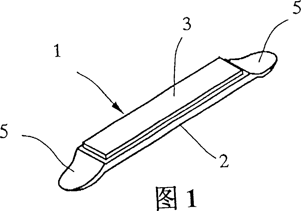
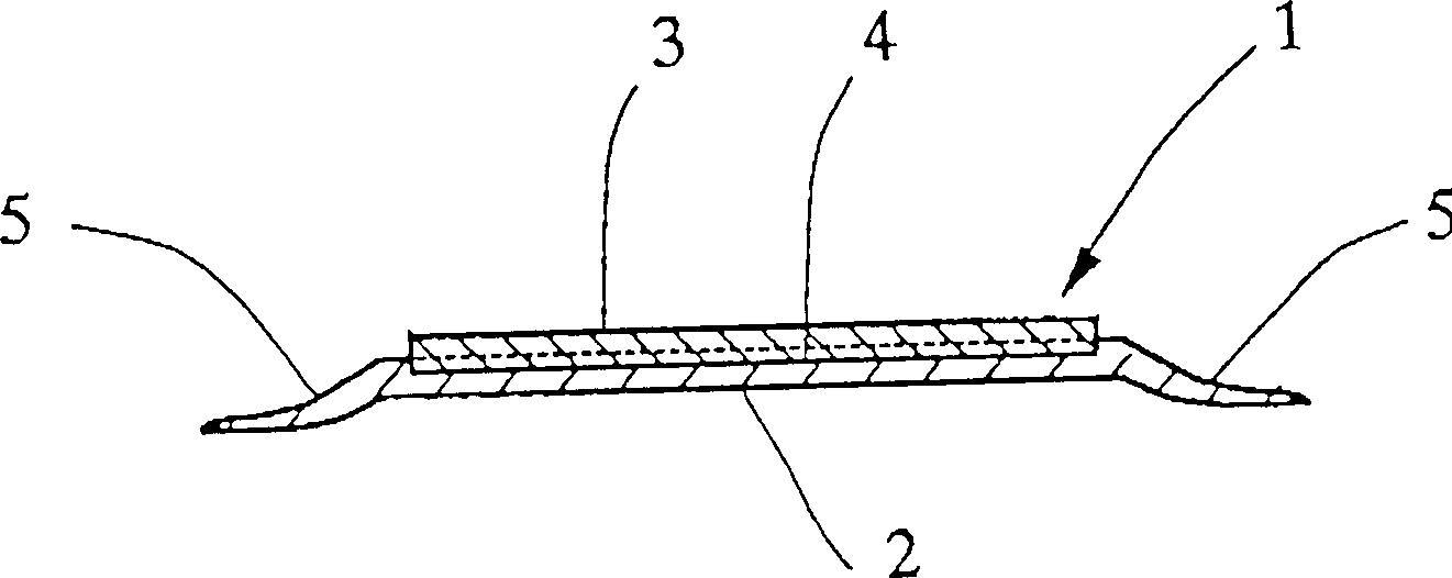
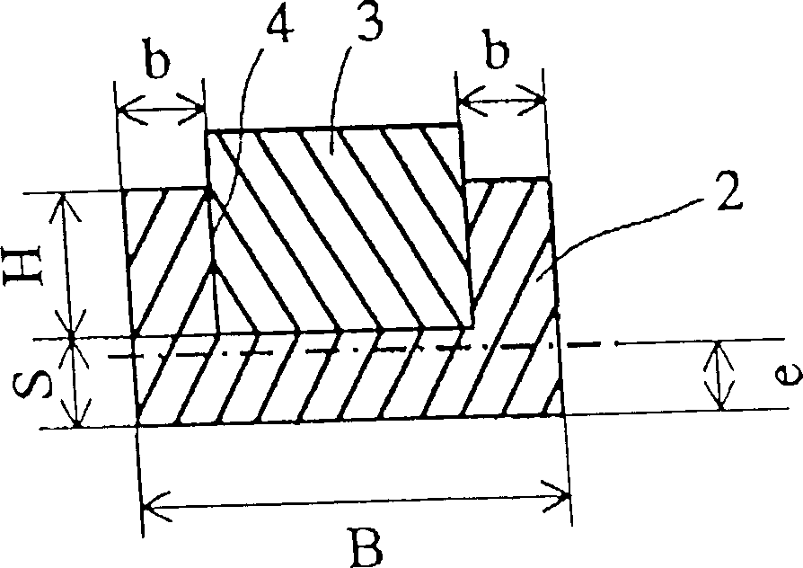
[0025] Figure 1 is a perspective view of an embodiment of the tissue box fixing member of the present invention, figure 2 It is a cross-sectional explanatory view parallel to the length direction of the central part of the tissue box holder shown in FIG. 1, image 3 It is an explanatory view of an enlarged cross-section perpendicular to the longitudinal direction of the central part of the tissue box fixing member shown in Fig. 1, Figure 4 Is a perspective view of other embodiments of the tissue box fixing member of the present invention, Figure 5 for Figure 4 A cross-sectional explanatory view parallel to the length direction of the central part of the tissue box fixing member shown, Figure 6 To represent Figure 4 A perspective explanatory diagram showing the relationship between the tissue box fixing member and the tissue box, Figure 7 To...


PUM


Abstract

The invention provides a holder for a tissue box which is used to attach the tissue box to a steel plate such as a refrigerator by utilizing the magnetic force of a magnet while being fitted on the rear surface of the tissue box, is compact and has a simple structure, does not have a movable section, and of which the attaching work is easily performed, and in addition, by which a stable attaching strength can be obtained. For this holder 1 for the tissue box, a guide section 5 is integrally formed on both ends in the longitudinal direction of a main body 2 made of a plastic having a slight flexibility. In this case, for the main body 2 made of the plastic, the flexible plate-shape magnet 3 is fixed in a recess provided on the surface, and the main body 2 has a rectangular plate-shape. For the guide section 5, the cross sectional shape in the longitudinal direction of the main body 2 forms a taper which tilts to the rear surface side toward the end section. The surface on which the plate-shape magnet 3 is fixed of the main body 2 preferably forms a recess-shape curved surface in the longitudinal direction.

Description

Invention field [0001] The present invention relates to a tissue box fixing member which is installed on the back of a paper tissue box formed by a combination of cardboard or plate-shaped plastic, and uses the magnetic force of a magnet to stick on a steel plate of a refrigerator or the like. Background technique [0002] In the past, there have been various proposals regarding the use of the magnetic force of a magnet to mount the tissue box fixing member of the tissue box. Because these tissue box holders using the magnetic force of magnets can be installed on the adsorbed body formed by ferromagnetic bodies such as the iron plate on the outer wall of the refrigerator through the magnetic force of the magnet, the tissue box can be conveniently installed in the required place as a background The technical publication No. 62-31032 describes that a box-shaped body with embedded magnets on the bottom covers the bottom of the tissue box, and at the same time, a plurality of fasteni...

Claims


Application Information

Patent Timeline
Patent Type & Authority Applications(China)
IPC IPC(8): A47K10/42A47K10/18B65D25/22
Inventor 小林郁夫高津尚子菅沼俊成前桥清中村辰夫吉野仁史前野和雄中山昌幸藤井一正
Owner CRECIA CORP
Why Eureka
Try Eureka