Sheet discharging device and image forming apparatus including the sheet discharging device

a technology of discharging device and image forming apparatus, which is applied in the direction of electrographic process apparatus, thin material handling, instruments, etc., can solve the problems of extreme deterioration of sheet dischargeability, and achieve the effect of improving the discharged sheet loading performance and preventing uneven brightness

Inactive Publication Date: 2010-02-11
CANON KK
View PDF16 Cites 18 Cited by
  • Summary
  • Abstract
  • Description
  • Claims
  • Application Information

AI Technical Summary

Benefits of technology

[0021]According to the present invention, a pair of sheet discharge rollers has an elastic layer. The sheet is nipped and discharged by the pair of sheet discharge rollers in a convex shape (U-shaped curve) in a width direction, whereby the rigidity of the sheet in the sheet discharging direction increases, the posture of the discharged sheet is stabilized, and the loading performance of the discharged sheet is improved. The sheet and the roller surface are evenly in contact with each other by the elastic layer, at least one elastic layer is formed of a foamed material, of the pair of sheet discharge rollers, and thus, the uneven brightness can be prevented when an image is fixed onto the sheet. Further, since the corner portions of the roller are not in contact with the sheet, the traces of the rollers are prevented from being left on the sheet.

Problems solved by technology

Thus, the sheet to be discharged subsequently cannot be normally discharged, and the sheet P1 is highly likely to be pushed outside the sheet discharge tray 60, or sheet jamming easily occurs, resulting in extreme deterioration of sheet dischargeability.

Method used


Image

  • Sheet discharging device and image forming apparatus including the sheet discharging device
  • Sheet discharging device and image forming apparatus including the sheet discharging device
  • Sheet discharging device and image forming apparatus including the sheet discharging device

Examples


first embodiment

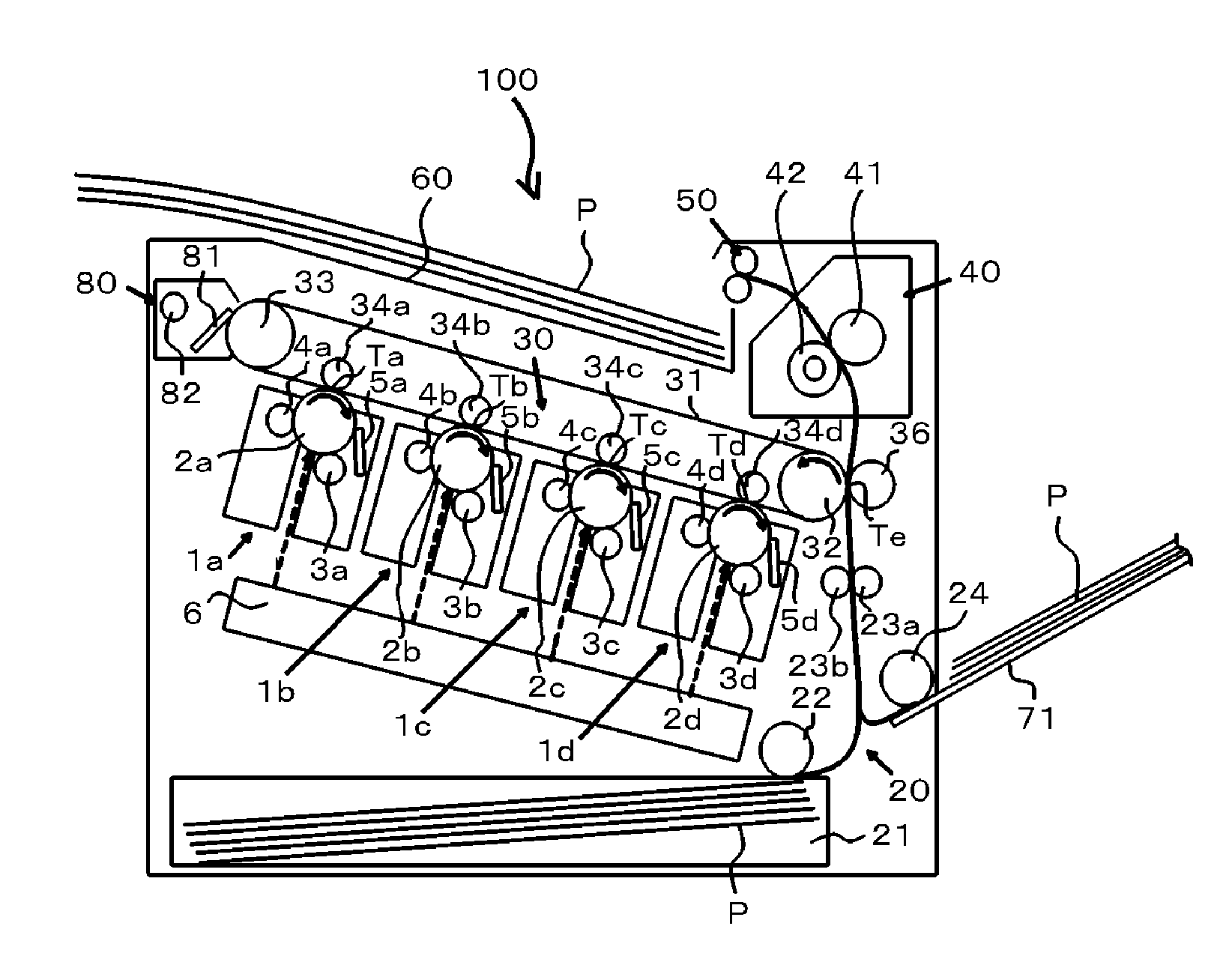
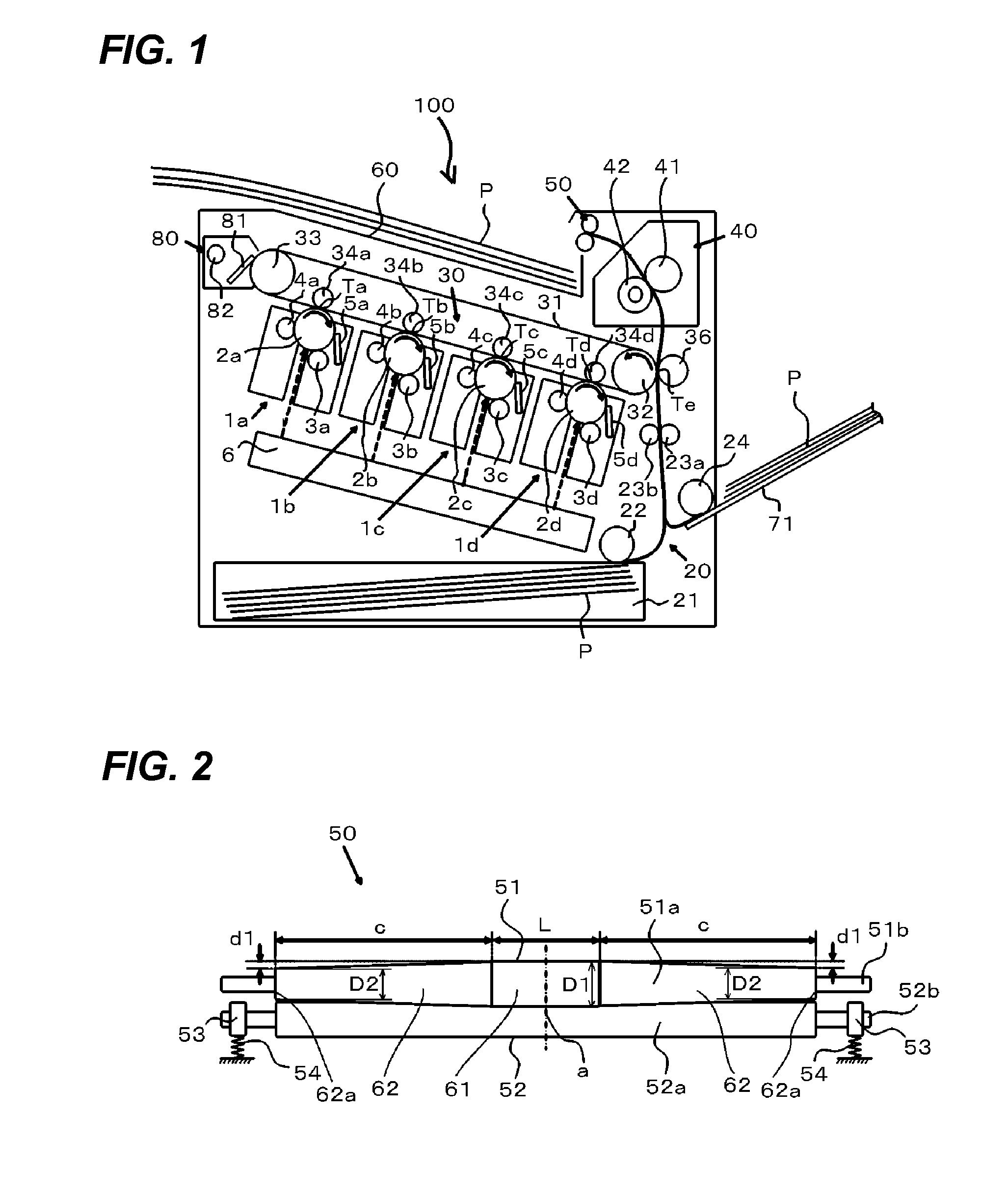
[0030]FIG. 1 is a cross-sectional view illustrating a configuration of an image forming apparatus 100 according to the first embodiment of the present invention. The image forming apparatus 100 is a color image forming apparatus using an electrophotographic image forming process.

[0031]As illustrated in FIG. 1, the image forming apparatus 100 includes an image forming portion 1a for forming a yellow image and an image forming portion 1b for forming a magenta image. The image forming apparatus 100 further includes an image forming portion 1c for forming a cyan image and an image forming portion 1d for forming a black image. The image forming apparatus 100 includes those four image forming portions (image forming unit). Those four image forming portions 1a, 1b, 1c, and 1d are arranged in a row at a constant interval. The image forming portions 1a, 1b, 1c, and 1d respectively include drum-type electrophotographic photoreceptor (hereinafter referred to as photosensitive drums) 2a, 2b, 2c...

second embodiment

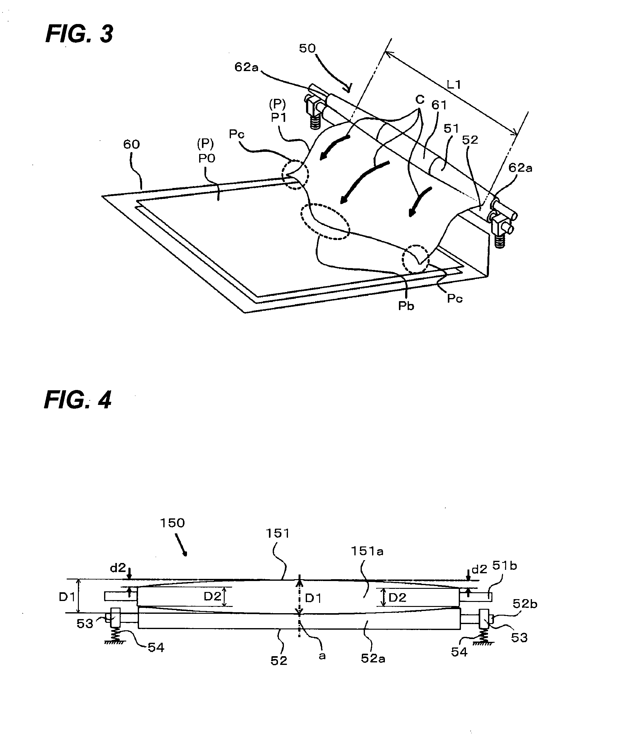
[0059]FIG. 4 is an enlarged side elevational view illustrating a configuration of a sheet discharging unit 150, used in the image forming apparatus according to the second embodiment of the present invention, as viewed from the downstream side in the conveyance direction of the sheet P. The sheet discharging unit 150 is different from the sheet discharging unit 50 of the first embodiment in the use of a sheet discharge drive roller 151 instead of the sheet discharge drive roller 51. In the sheet discharging unit 150, the same components and effects as those in the sheet discharging unit 50 are denoted by the same reference numerals, and the description is suitably omitted. Also in the second embodiment, the image forming apparatus similar to that of the first embodiment can be used, and thus the description of the image forming apparatus is omitted.

[0060]As illustrated in FIG. 4, the sheet discharging unit 150 is constituted of a sheet discharge drive roller 151 and a sheet discharg...


PUM

PropertyMeasurementUnit
widthaaaaaaaaaa
sizeaaaaaaaaaa
outer diameteraaaaaaaaaa

Abstract

In a sheet discharging unit including a pair of sheet discharge rollers which discharges a sheet P, the outer diameter of a sheet discharge drive roller included in the pair of sheet discharge rollers is set so that the outer diameter of a straight portion which is a central portion in the width direction perpendicular to the discharging direction of the sheet P is larger than the outer diameters of both end portions in the width direction. Further, in the sheet discharging unit, the pair of sheet discharge rollers respectively include metal shafts extending in the width direction and elastic layers respectively wound around the metal shafts and continuously formed to be longer in the width direction than the width of a sheet P with a passable maximum size. Further, at least one elastic layer of the pair of sheet discharge rollers is formed of a foamed material.

Description

BACKGROUND OF THE INVENTION[0001]1. Field of the Invention[0002]The present invention relates to a sheet discharging device of an image forming apparatus, which uses an electrostatic recording system and an electrophotographic recording system, and an image forming apparatus including the sheet discharging device.[0003]2. Description of the Related Art[0004]Recently, an image forming apparatus has reduced in size and realized high performance, and an intermediate transfer type full-color image forming apparatus having the constitution disclosed in U.S. Pat. No. 6,970,665 has been developed. The invention disclosed in U.S. Pat. No. 6,970,665 is described with reference to FIG. 5 of the present application.[0005]As illustrated in FIG. 5, an image forming apparatus 200 includes a plurality of image forming portions 10. The image forming portions 10 form a latent image on photosensitive drums 11, which are image bearing members, with the use of light, magnetism, and charge to elicit the...

Claims


Application Information

Patent Timeline
Patent Type & Authority Applications(United States)
IPC IPC(8): B65H29/22
CPCB65H29/14B65H29/70B65H2301/44318B65H2301/51214B65H2301/5122B65H2401/111G03G15/6573B65H2404/1312B65H2404/1314B65H2404/143B65H2801/06G03G15/6552B65H2401/242G03G15/00
Inventor SAHARA, HIROSHISETORIYAMA, TAKESHI
Owner CANON KK
Why Eureka
Try Eureka