Edge lighting back light unit

a back light unit and edge lighting technology, applied in the field of back light units, can solve the problems of uneven light emission of blu, ccfl also suffers inconvenience, and alternating currents adversely affect the image signal of the lcd

Inactive Publication Date: 2010-02-11
ADVANCED OPTOELECTRONICS TECH
View PDF11 Cites 93 Cited by
  • Summary
  • Abstract
  • Description
  • Claims
  • Application Information

AI Technical Summary

Problems solved by technology

Though the CCFL possesses good luminance, it makes the BLU suffers uneven light emission because the luminance at two ends of the CCFL is inferior to that at center of the CCFL.
The CCFL also suffers inconvenience when being adapted to a portable display because it must be provided with high voltages and alternating currents.
Furthermore, it is found that alternating currents adversely affect image signals of the LCD.
The CCFL further has disadvantages of lower light utilization efficiency due to its cylinder shape and short life cycle due to its susceptibility to temperature.
In addition, the LCD adapted with the CCFL has higher cost.
However, the prior arts as mentioned above still possess drawbacks such as inferior coupling efficiency of the light guide bar with the point illuminants, complicated design of the light guide bar, and inferior illumination uniformity.
However, the BLU requires a large number of LEDs, accordingly component failure rate is increased.
Furthermore, optical anomaly is easily resulted because the linear illuminant is formed by arranging the plurality of point illuminants, which are the LEDs, in a straight line.
Additionally, the arrangement of the LEDs has drawbacks such as poor heat dissipation and complicated assembling processes.

Method used


Image

  • Edge lighting back light unit
  • Edge lighting back light unit
  • Edge lighting back light unit

Examples


Embodiment Construction

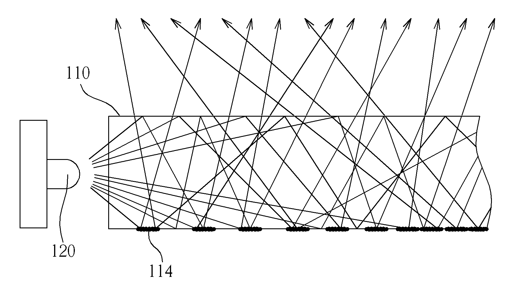
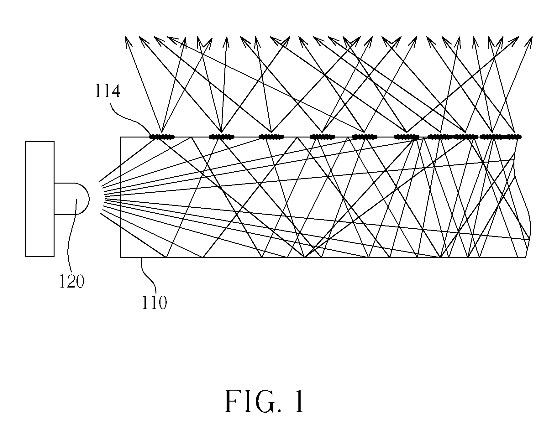
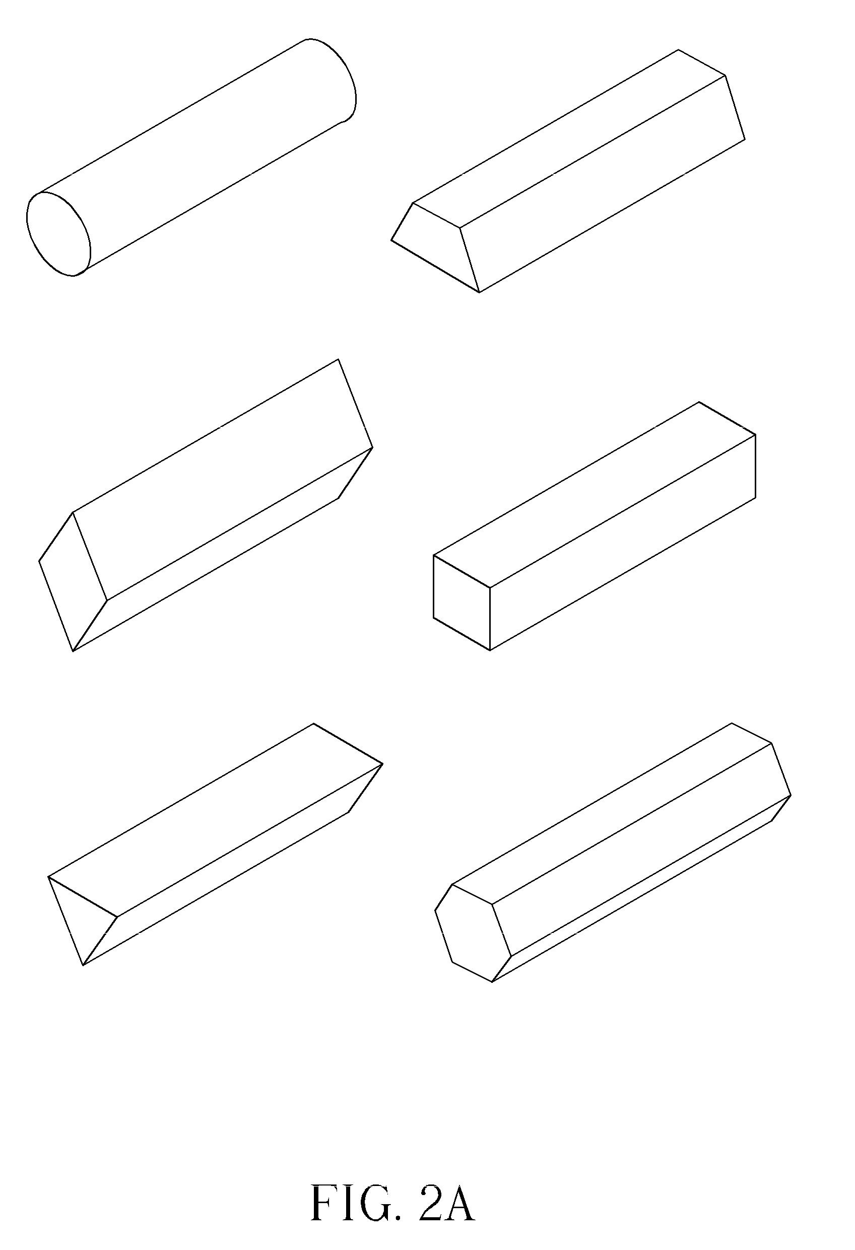
[0023]The present invention is to provide an edge lighting BLU. In the following, detailed description along with the accompanied drawings is given to better explain preferred embodiments of the present invention but not limited to this. On the other hand, details well-known to those skilled in the art is omitted to avoid unnecessary limitation. Embodiments are provided so that this disclosure will be thorough and complete. However, the present invention can be embodied in many different forms and should not be construed as limited to the embodiments set forth herein. It is to be understood that both the foregoing general description and the following detailed description are exemplary and explanatory only and are not restrictive of the invention, as claimed.

[0024]U.S. Pat. No. 6,655,825 discloses a white light source for LCD backlight. The white light source is provided by mixing red, green and blue lights in the first end of an optical fiber to produce white light and then conduct...


PUM


Abstract

An edge lighting back light unit (BLU) includes at least a point illuminant, a light guide unit, and a light guide plate. The light guide unit includes a plurality of micro-structures for breaking the total reflection inside the light guide unit to generate a uniform linear light illuminating outside the light guide unit. Then, the light guide plate could reflect the light from the linear illuminant to form a uniformly planar illuminant. The edge lighting BLU in the present invention could reduce the components, lower the temperature, and avoid the light mura.

Description

BACKGROUND OF THE INVENTION [0001]1. Field of the Invention[0002]The present invention relates to a back light unit, and more particularly, to an edge lighting back light unit (BLU).[0003]2. Description of the Prior Art[0004]With progress in electronic technology and the popularization of portable electronic devices in daily life, demands for display of light weight and low power consumption have been increased. Therefore the liquid crystal display (LCD) has gradually replaced the cold cathode tube (CRT) display in modern information products such as portable computers, mobile phones and personal digital assistants (PDA), based on its advantages of low power consumption, low heat emissions, light weight and non-radiative.[0005]Because liquid crystals are not self-illuminant, back light unit (BLU) is provided to enable the display function. A conventional BLU includes an illuminant / light source and a light guide plate. The illuminant is positioned corresponding to the light guide pla...

Claims


Application Information

Patent Timeline
Patent Type & Authority Applications(United States)
IPC IPC(8): F21V8/00F21V7/04
CPCG02B6/001G02B6/0036G02B6/0085G02B6/0061G02B6/0065G02B6/0041
Inventor CHIU, KUAN-HERCHEN, IRENE
Owner ADVANCED OPTOELECTRONICS TECH
Why Eureka
Try Eureka