
Film forming method and film forming apparatus

Active Publication Date: 2010-02-11
TOKYO ELECTRON LTD
View PDF8 Cites 9 Cited by
  • Summary
  • Abstract
  • Description
  • Claims
  • Application Information

AI Technical Summary

Benefits of technology

[0011]To solve the above and/or other problems, the present invention provides a film forming method and a fil

Problems solved by technology

Furthermore, since some devices have limits in thermal budget, a film which may be formed or crystallized at a low temperature is demanded.
However, when a dielectric film is crystallized as described above, leakage current increases due to leakage from grain boundaries of crystals.

Method used


Image

  • Film forming method and film forming apparatus
  • Film forming method and film forming apparatus
  • Film forming method and film forming apparatus

Examples


Embodiment Construction

[0030]Hereinafter, the present invention will be described in detail by explaining exemplary embodiments of the invention with reference to the attached drawings.

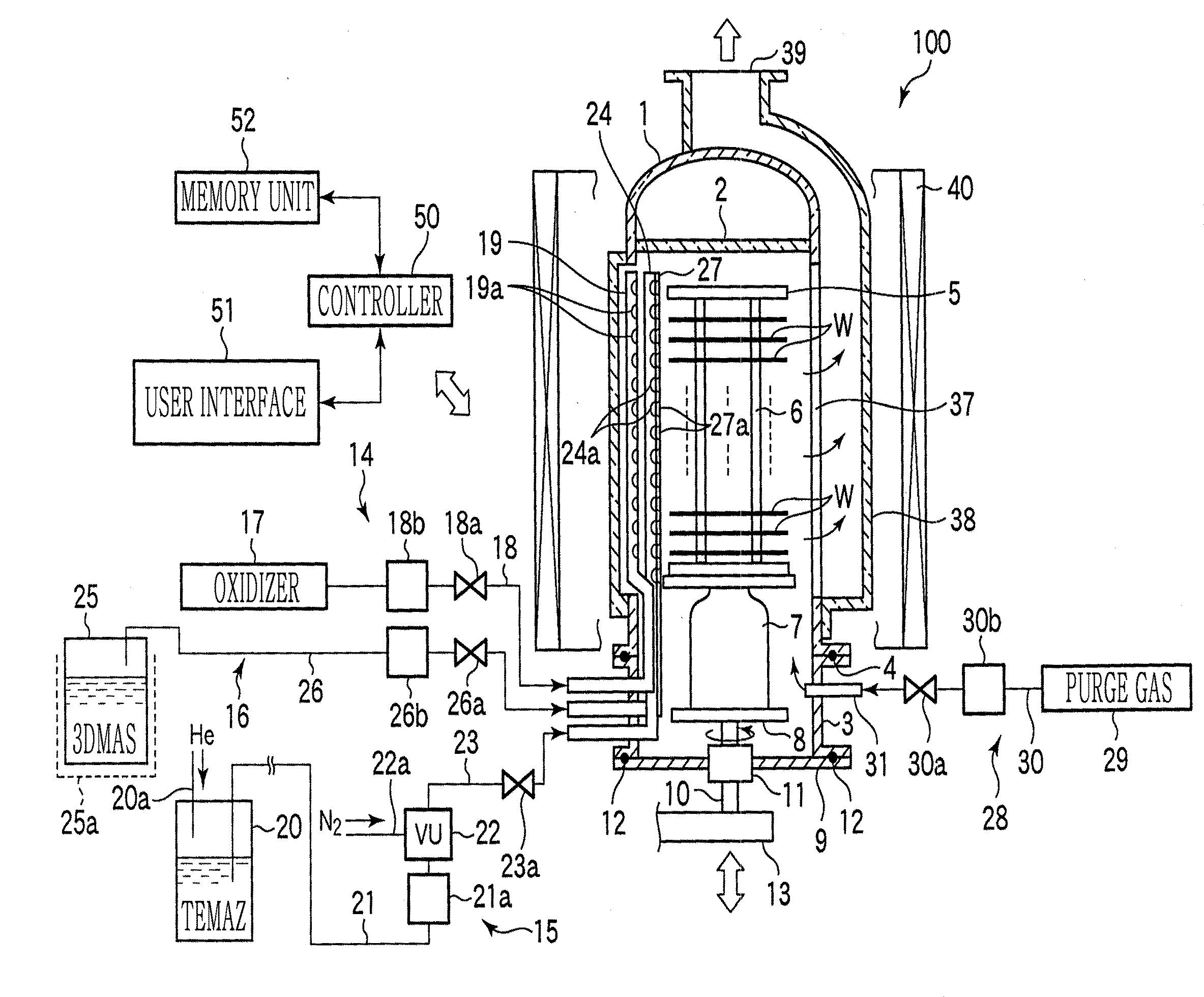
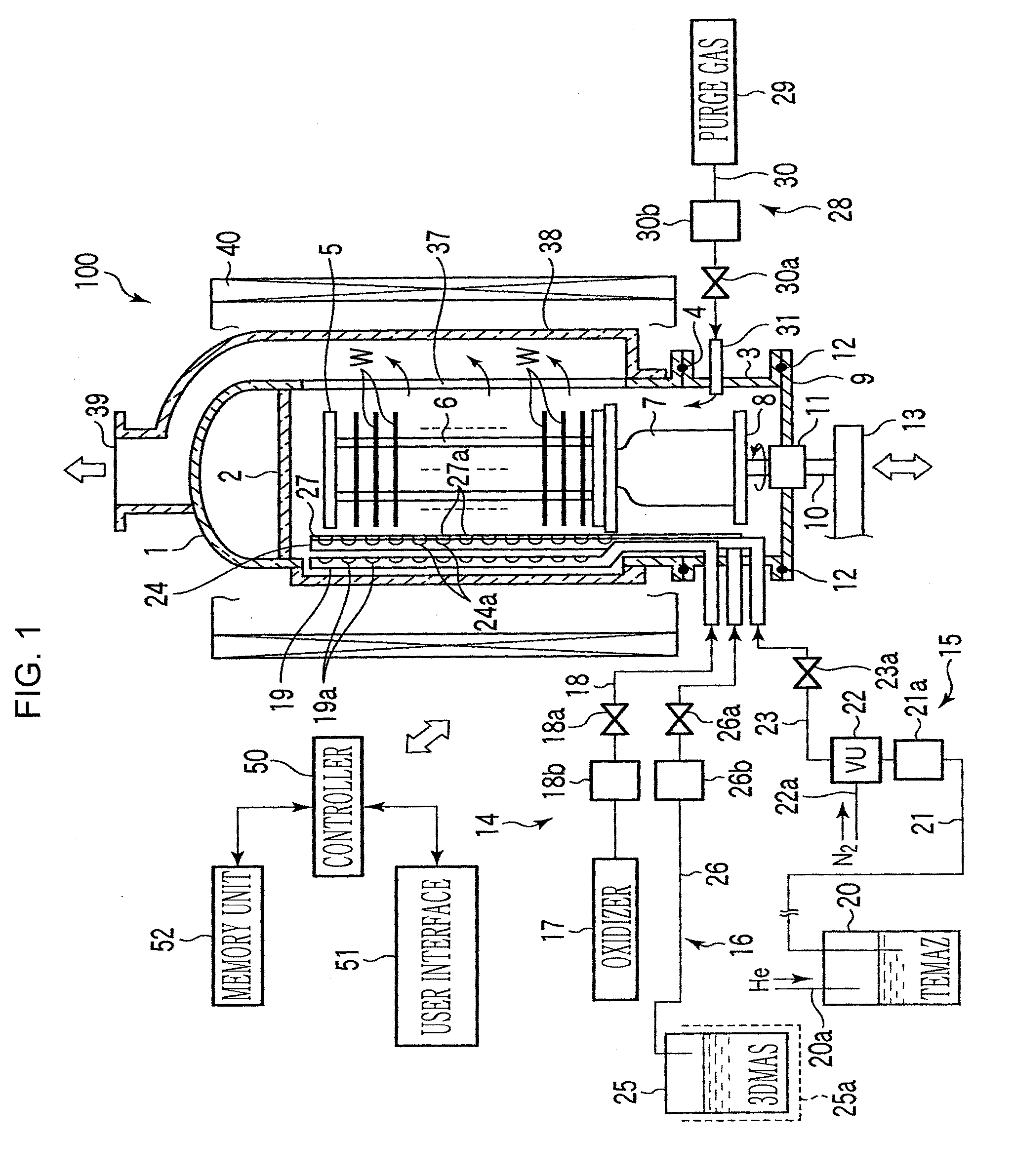
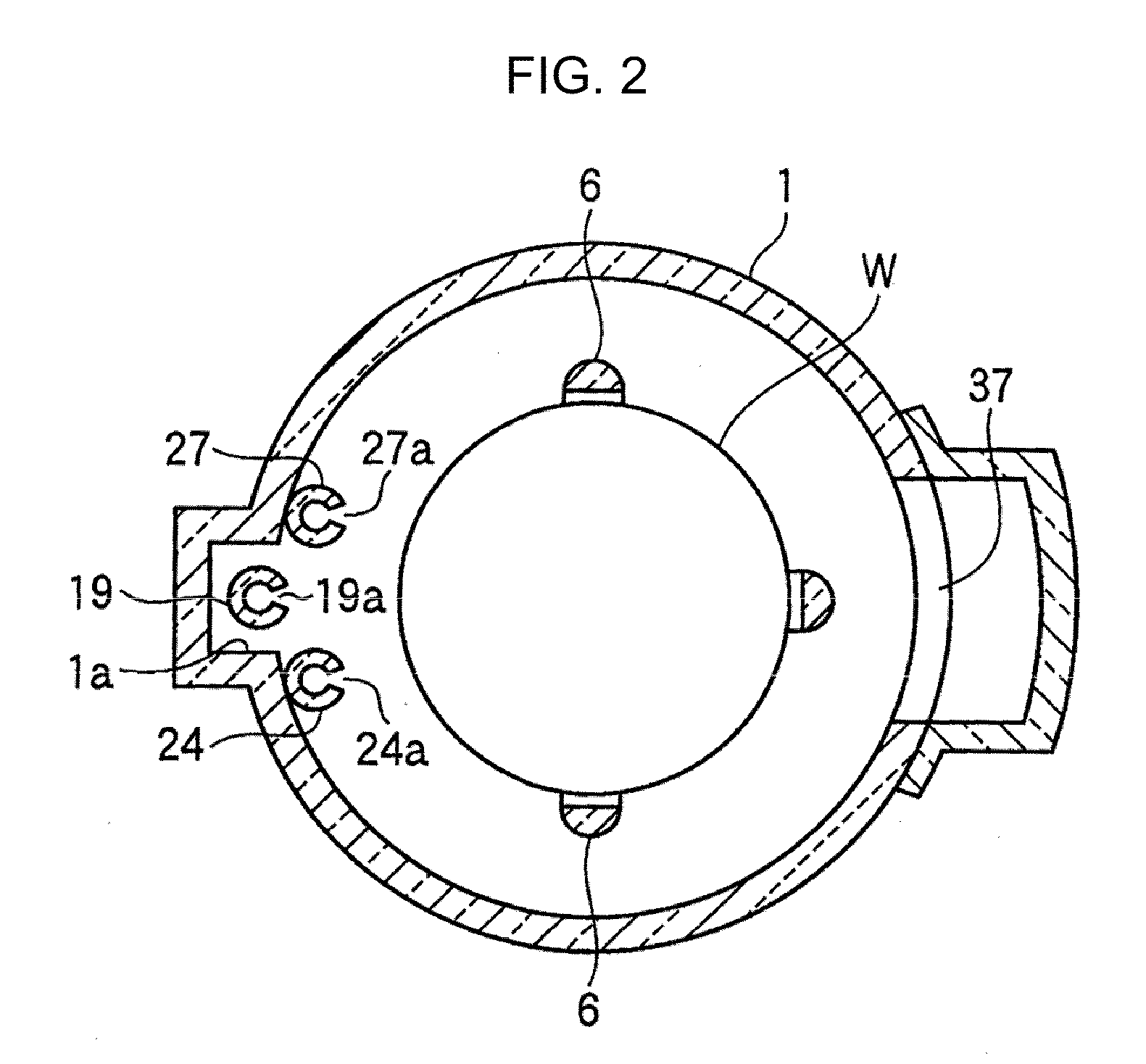
[0031]FIG. 1 is a longitudinal sectional view of a film forming apparatus for executing a film forming method according to an embodiment of the present invention, FIG. 2 is a cross-sectional view of the film forming apparatus of FIG. 1, and FIG. 3 is a timing chart showing timings of gas supply performed in a film forming method according to an embodiment of the present invention. Furthermore, a heating unit is omitted in FIG. 2.

[0032]The film forming apparatus 100 includes a cylindrical processing vessel 1 of which bottom is open and which has a ceiling. The processing vessel 1 is entirely formed of quartz, for example, and a top plate 2 formed of quartz is formed at the ceiling of the processing vessel 1 and seals the ceiling of the processing vessel 1. Furthermore, a manifold 3, which may be formed of stainless steel and...


PUM

PropertyMeasurementUnit
Temperatureaaaaaaaaaa
Concentrationaaaaaaaaaa

Abstract

The invention includes inserting an object to be processed into a processing vessel, which can be maintained vacuum, and making the processing vessel vacuum; performing a sequence of forming a ZrO2 film on a substrate by alternately supplying zirconium source and an oxidizer into the processing vessel for a plurality of times and a sequence of forming SiO2 film on the substrate by alternately supplying silicon source and an oxidizer into the processing vessel for one or more times, wherein the number of times of performing each of the sequences is adjusted such that Si concentration of the films is from about 1 atm % to about 4 atm %; and forming a zirconia-based film having a predetermined thickness by performing the film forming sequences for one or more cycles, wherein one cycle indicates that each of the ZrO2 film forming sequences and the SiO2 film forming sequences are repeated for the adjusted number of times of performances.

Description

CROSS-REFERENCE TO RELATED PATENT APPLICATIONS[0001]This application claims the benefit of Japanese Patent Application No. 2008-206976, filed on Aug. 11, 2008, in the Japan Patent Office, the disclosure of which is incorporated herein in its entirety by reference.BACKGROUND OF THE INVENTION[0002]1. Field of the Invention[0003]The present invention relates to a method and an apparatus for forming a zirconia-based film on a substrate to be processed, such as a semiconductor wafer.[0004]2. Description of the Related Art[0005]Recently, due to demands for higher integration and higher operating speed of a large scale integration (LSI), design rules of semiconductor devices that constitute a LSI are becoming finer. Along with the demands, there are also demands for increased capacity of capacitors that are used in dynamic random access memories (DRAMs) and demands for increased permittivity of dielectric films. It is necessary to crystallize such dielectric films to obtain higher permitti...

Claims


Application Information

Patent Timeline
IPC IPC(8): H01L21/31
CPCC23C16/40H01L21/31641C23C16/45546C23C16/45529H01L21/02189H01L21/02164H01L21/0228H01L21/022H01L21/02181H01L21/0262H01L21/02356
Inventor ISHIDA, YOSHIHIROHARADA, KATSUSHIGESUGAWARA, TAKUYA
Owner TOKYO ELECTRON LTD
Learn More