
In-cell touch display device and operating method thereof

Active Publication Date: 2017-05-04
AU OPTRONICS CORP
View PDF3 Cites 3 Cited by
  • Summary
  • Abstract
  • Description
  • Claims
  • Application Information

AI Technical Summary

Benefits of technology

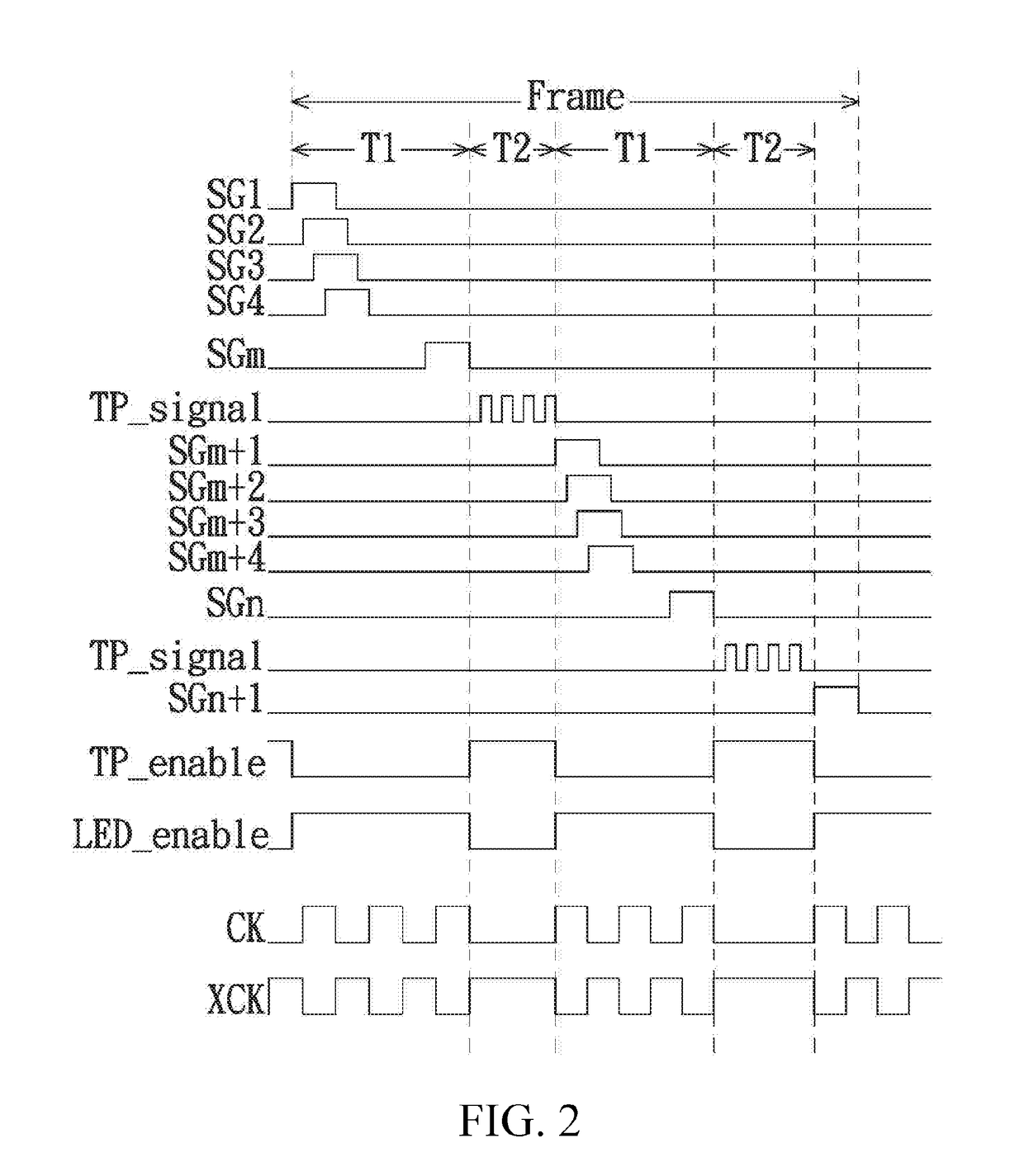
The present invention relates to an in-cell touch display device that reduces the occurrence of a striped pattern problem. The device includes a control circuit that defines a plurality of gate line driving periods and at least one touch sensing period in a frame period. During the touch sensing period, the control circuit drives gate lines sequentially and turns on the backlight module to provide illumination. The control circuit also controls the touch processing circuit to output a driving signal to all touch sensing units and to temporarily stop driving gate lines for maintaining a high level of a gate pulse generated by a shift register. The technical effects of the invention are to reduce the occurrence of a striped pattern problem and to provide stable and reliable operation of the in-cell touch display device.

Problems solved by technology

However, leakage exists along the plurality of transistors in the shift register; as a result, the gate potential and the gate pulse generated by the shift register is lower than a preset level, which causes a striped pattern problem on a frame.
Therefore, each time the in-cell touch display device operates in a touch sensing period, although a level of a gate of a driving transistor in a shift register that corresponds to the first gate line driven after the current touch sensing period and is in a gate driving circuit of the in-cell touch display device needs to be maintained for a preset period of time, transistors in the shift register at this stage lack illumination due to turn-off of the backlight module within the preset period of time, and therefore has a small leakage current.

Method used


Image

  • In-cell touch display device and operating method thereof
  • In-cell touch display device and operating method thereof
  • In-cell touch display device and operating method thereof

Examples


Embodiment Construction

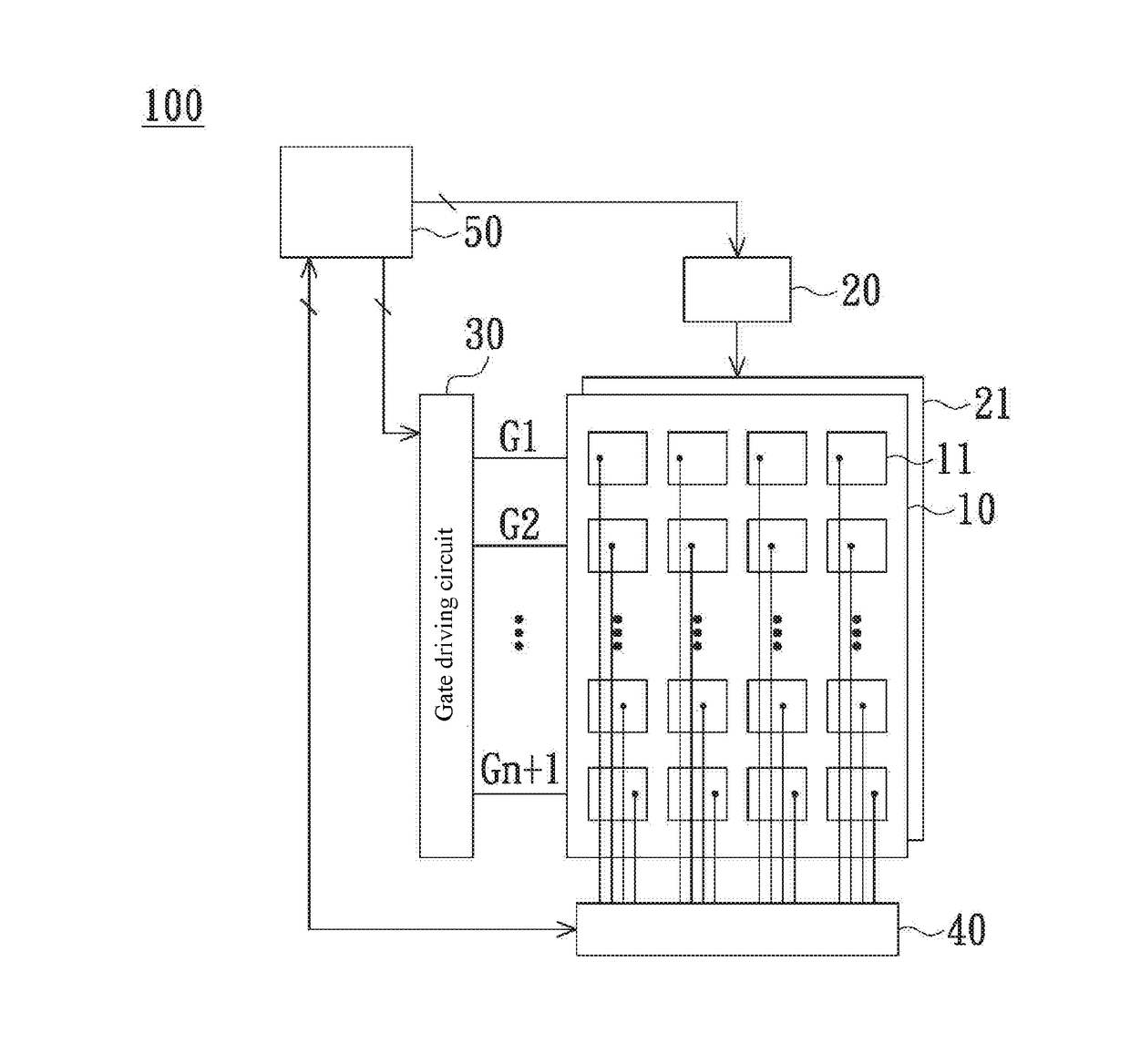
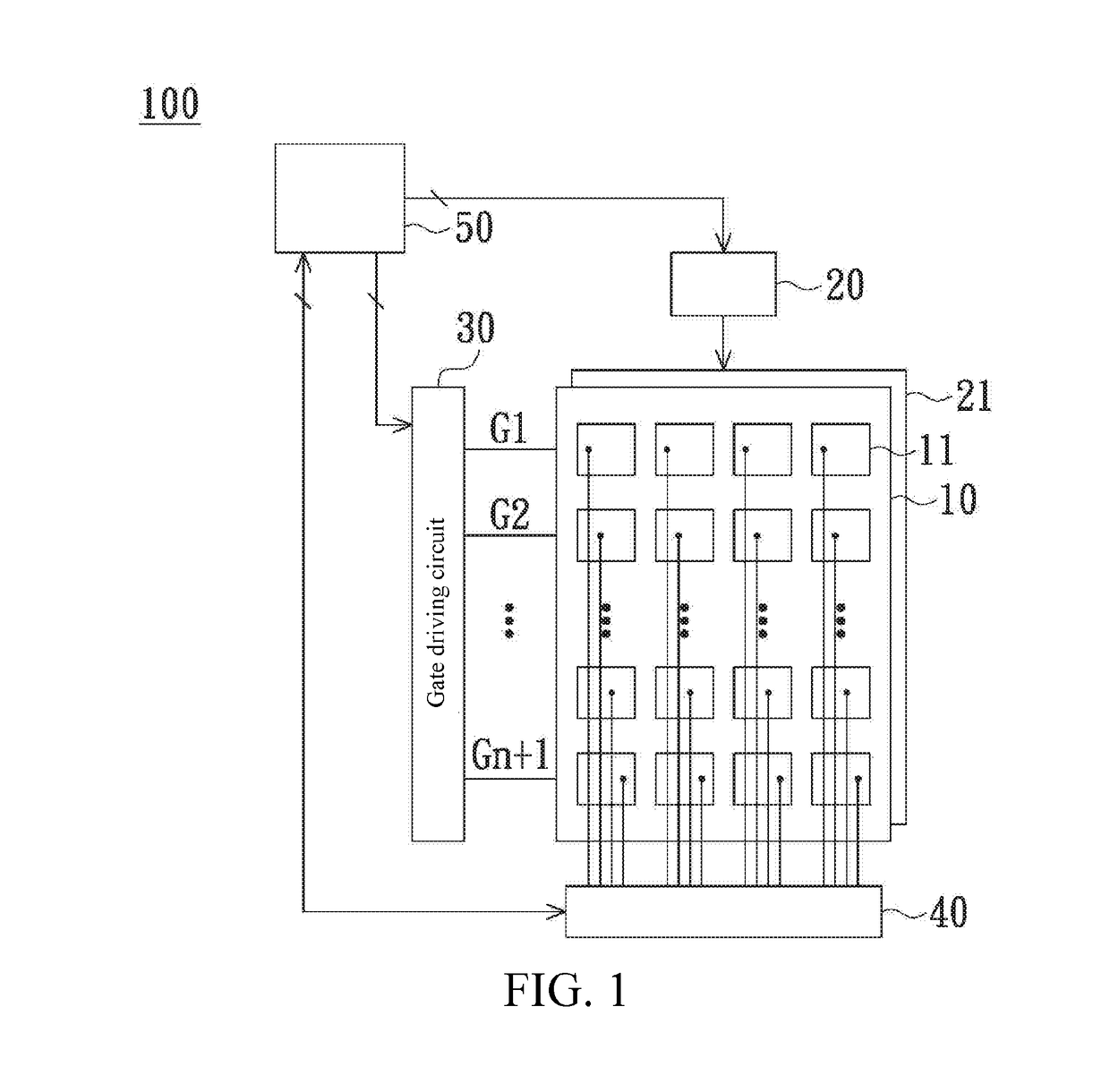
[0012]Refer to FIG. 1, which is a schematic diagram of an in-cell touch display device according to an embodiment of the present invention. An in-cell touch display device 100 includes an in-cell touch panel 10, a backlight module driving circuit 20, a backlight module 21, a gate driving circuit 30, a touch processing circuit 40, and a control circuit 50. The in-cell touch panel 10 includes a plurality of gate lines G1 to Gm and a plurality of touch sensing units (as shown by label 11). The gate driving circuit 30 is electrically coupled to the gate lines G1 to Gm. The touch processing circuit 40 is electrically coupled to each touched sensing unit 11. The control circuit 50 is electrically coupled to the gate driving circuit 30, the touch processing circuit 40, and the backlight module driving circuit 20.

[0013]The control circuit 50 can control the touch processing circuit 40 to output a driving signal to all the touch sensing units 11, and the driving signal returns to the touch p...


PUM


Abstract

An in-cell touch display device includes an in-cell touch panel, a backlight module driving circuit, a backlight module, a gate driving circuit, a touch processing circuit and a control circuit. The in-cell touch panel includes a plurality of gate lines and a plurality of touch sensing units. The control circuit is used for defining a plurality of gate line driving periods separated from each other in the time and at least one touch sensing period in a frame period. The touch sensing period is between two adjacent gate line driving periods. During the gate line driving periods, the control circuit controls the gate driving circuit to drive the gate lines sequentially and outputs a signal to the backlight module driving circuit to turn on the backlight module. During each touch sensing period, the control circuit controls the touch processing circuit to output a driving signal to the touch sensing units and outputs a signal to the backlight module driving circuit to turn off the backlight module.

Description

BACKGROUND[0001]Technical Field[0002]The present invention relates to a technology of display devices, and in particular, to an in-cell touch display device and operating methods thereof.[0003]Related Art[0004]There are two major technical development trends of touch display devices at present: an out-cell technology and an in-cell technology. In the out-cell technology, a display panel having no touch function is overlaid with a touch panel, while in the in-cell technology, a touch sensor is directly placed inside a pixel structure of a display panel. Compared with a touch display device using the out-cell technology, a touch display device using the in-cell technology has an advantage of thinner thickness.[0005]In an in-cell touch display device, at least one touch sensing period is inserted in each frame period, and during each touch sensing period, while the gate driving operation is suspended, a gate potential level of a driving transistor in a shift register needs to be mainta...

Claims


Application Information

Patent Timeline
IPC IPC(8): G06F3/041G06F3/044
CPCG06F3/0412G06F3/044G06F3/0416G06F3/04184G06F3/0443
Inventor YEH, PI-CHUNCHENG, CHING-SHENG
Owner AU OPTRONICS CORP
Learn More