Method and system for isolating software components

Active Publication Date: 2010-02-11
TYPEMOCK
View PDF5 Cites 47 Cited by
  • Summary
  • Abstract
  • Description
  • Claims
  • Application Information

AI Technical Summary

Benefits of technology

[0014]It would be easier to test such code if there were no need to change the design for te

Problems solved by technology

This is not always possible (due to security mean

Method used


Image

  • Method and system for isolating software components
  • Method and system for isolating software components
  • Method and system for isolating software components

Examples


Embodiment Construction

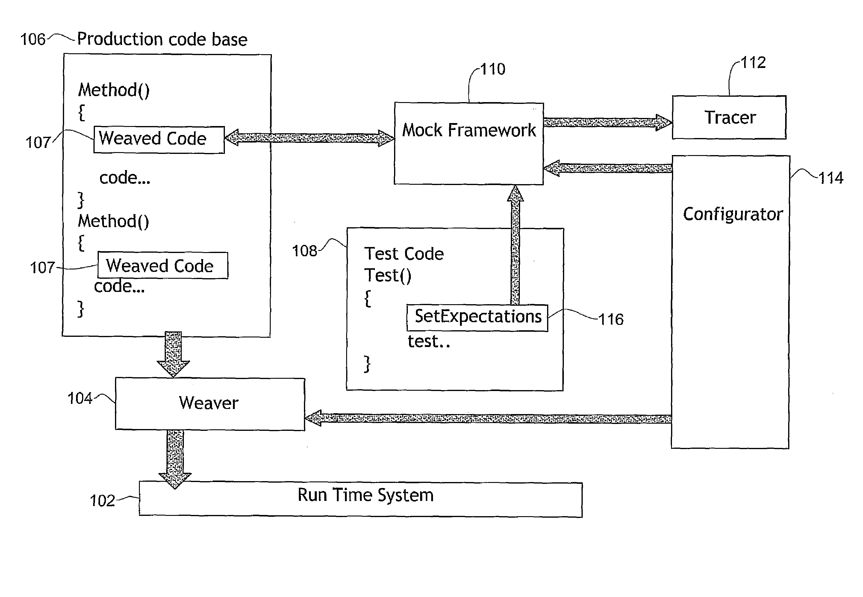
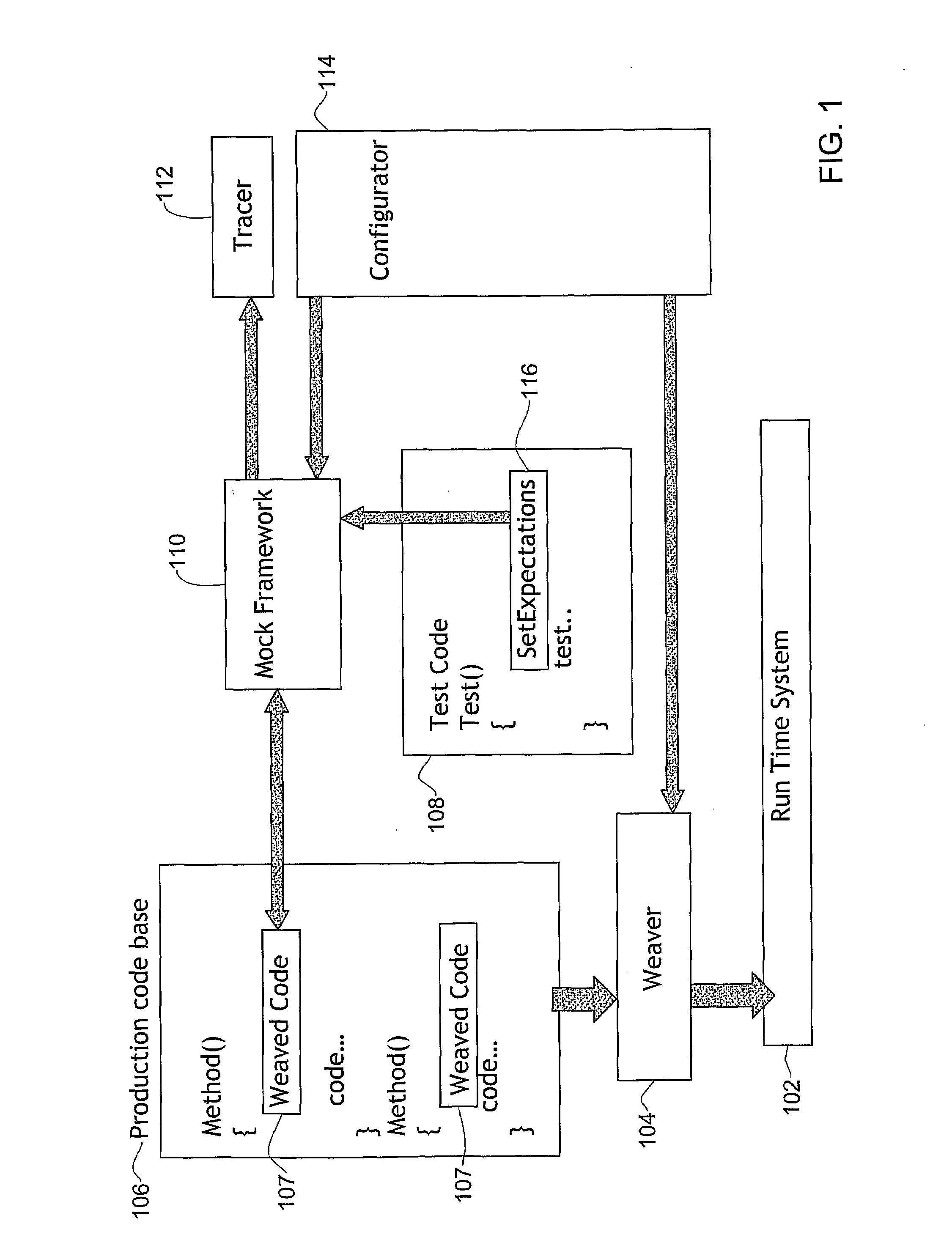
[0030]Reference is now made to FIG. 1 which is a simplified functional block diagram of a software isolation system constructed and operative in accordance with certain embodiments of the present invention. The run time system 102 is the system that actually runs the code and the tests; this could be an operating system, a scripting system or a virtual machine (as in Java or .NET). The weaver 104 is responsible for inserting the added hooking code into the production code base 106. In each method of the production code the weaver 104 may insert a small piece of code 107 that calls the Mock framework 110 which then decides whether to call the original code or to fake the call. The inserted code 107 can also modify the arguments passed to the production method if required. This is handy for arguments passed by reference.

[0031]The production code base 106 is the code that is to be isolated. There is no need to change the design of this code just to isolate the code. The test code 108 c...


PUM


Abstract

A software testing system operative to test a software application comprising a plurality of software components, at least some of which are highly coupled hence unable to support a dependency injection, each software component operative to perform a function, the system comprising apparatus for at least partially isolating, from within the software application, at least one highly coupled software component which performs a given function, and apparatus for testing at least the at least partially isolated highly coupled software component.

Description

REFERENCE TO CO-PENDING APPLICATIONS[0001]Priority is claimed from U.S. provisional application No. 60 / 826,759, entitled “Method and System for Isolating Software Components” and filed 25 Sep. 2006.FIELD OF THE INVENTION[0002]The present invention relates generally to validating software.BACKGROUND OF THE INVENTION[0003]Conventional Internet sources state that “Dependency Injection describes the situation where one object uses a second object to provide a particular capacity. For example, being passed a database connection as an argument to the constructor instead of creating one internally. The term “Dependency injection” is a misnomer, since it is not a dependency that is injected, rather it is a provider of some capability or resource that is injected.”[0004]Validating software is a complex problem that grows exponentially as the complexity of the software grows. Even a small mistake in the software can cause a large financial cost. In order to cut down on these costs, software c...

Claims


Application Information

Patent Timeline
IPC IPC(8): G06F11/36
CPCG06F11/3688G06F11/3668G06F11/3696
Inventor LOPIAN, ELI
Owner TYPEMOCK
Why Eureka
Try Eureka