Cable locking device and method

a technology of cable locking and cable, which is applied in the direction of screws, threaded fasteners, building repairs, etc., can solve the problems of large and noticeable locking devices, and the current cable locking devices often do not generate enough load ratings, so as to achieve the effect of higher cable load ratings

Inactive Publication Date: 2010-02-18
ERICO INT
View PDF99 Cites 20 Cited by
  • Summary
  • Abstract
  • Description
  • Claims
  • Application Information

AI Technical Summary

Benefits of technology

[0007]According to aspects of the invention, a cable locking device has one or more of the following characteristics: integral unlocking mechanism for keyless application—general and seismic applications; integral locking mechanism for safety reason—general and seismic applications; cable biting mechanism to generate higher cable load ratings for single barrel locking devices as well as seismic cable locking devices—general and seismic applications; single barrel locking device—general and seismic applications; single barrel locking device rive

Problems solved by technology

Possible shortcomings of prior systems include: locking device is too large and too noticeable from a distance; locking device requires a key to release and adjust the cable; ca

Method used


Image

  • Cable locking device and method
  • Cable locking device and method
  • Cable locking device and method

Examples


Embodiment Construction

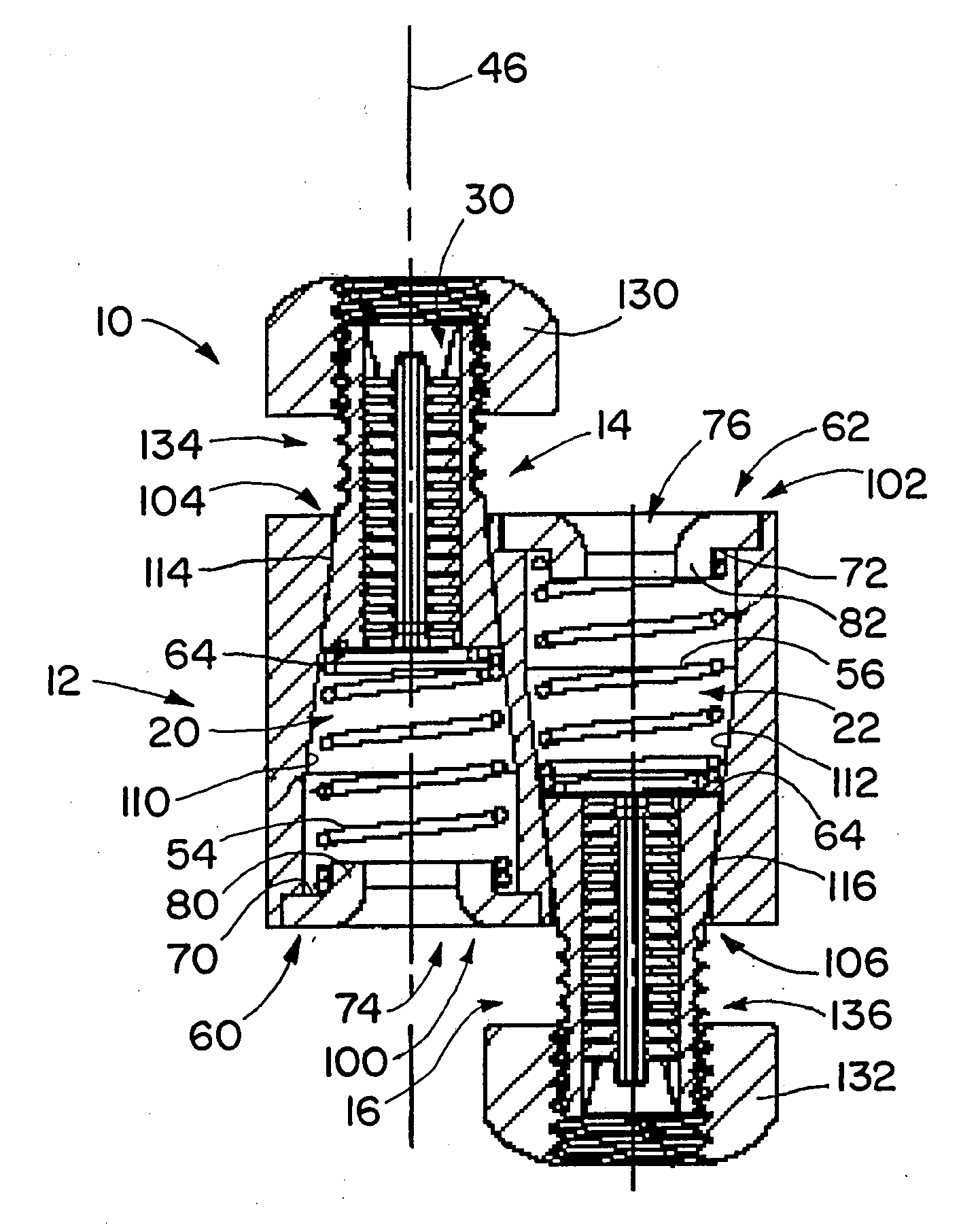
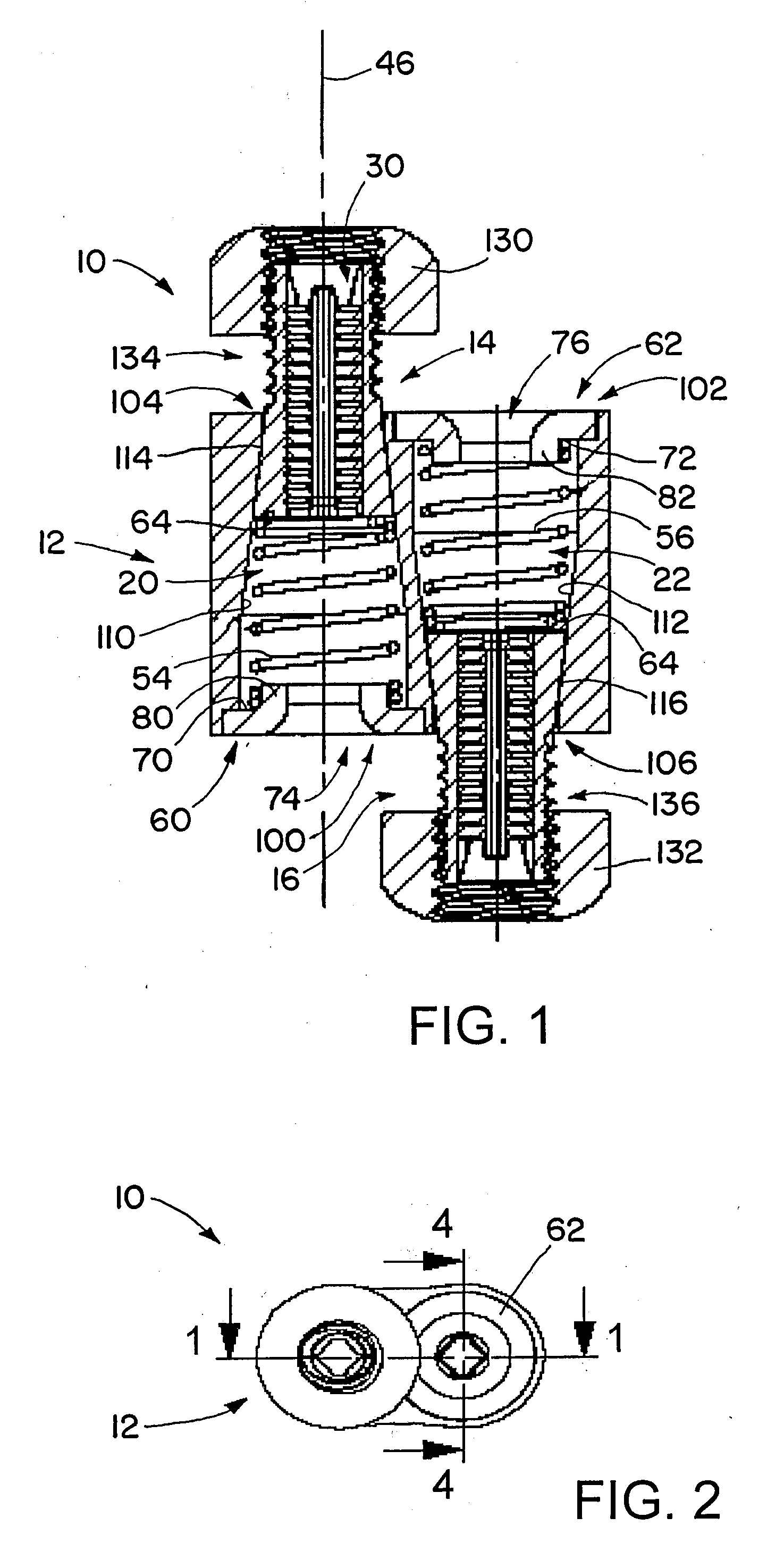
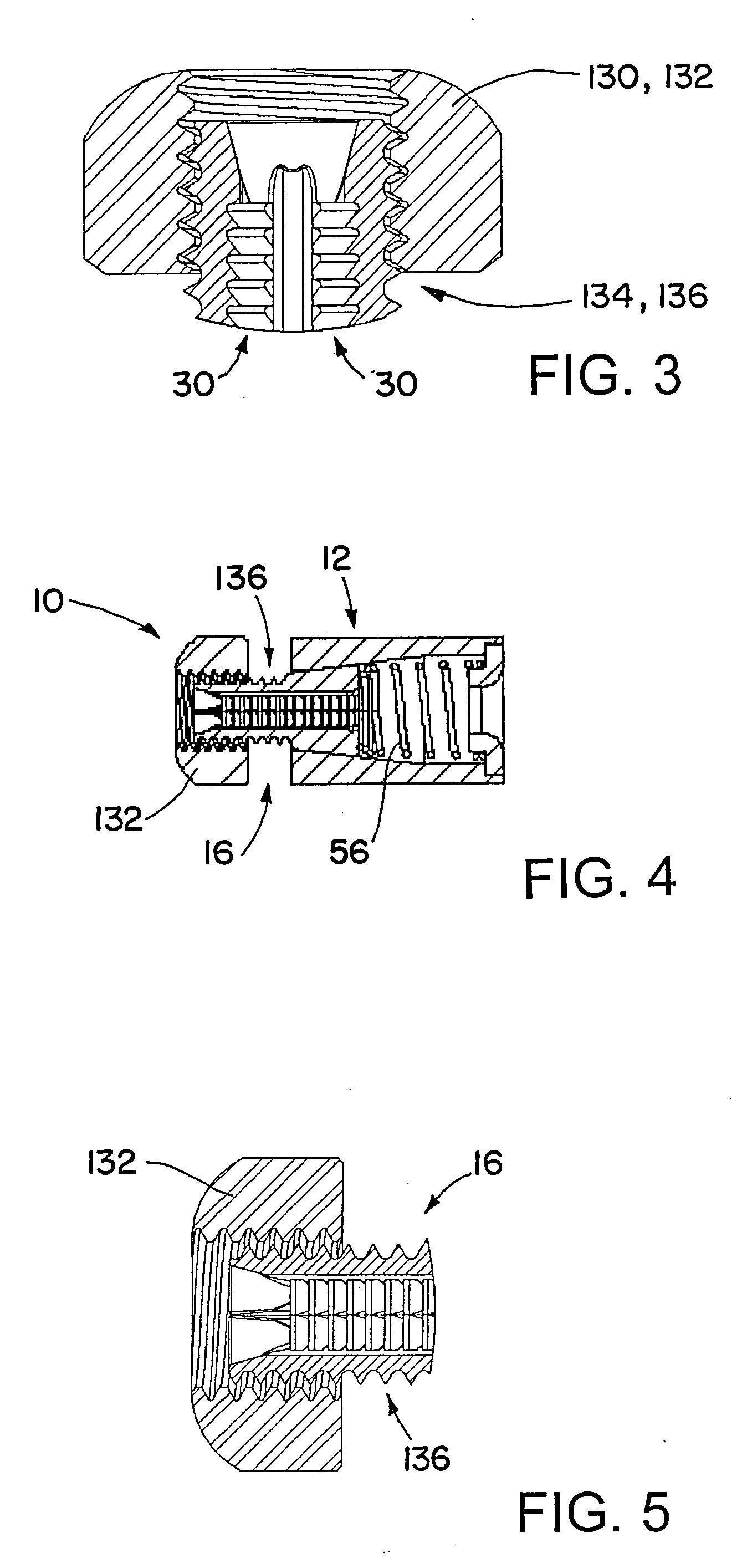
[0042]In order to meet all above requirements, a locking device has any of various configurations, such as those shown in the figures and described below. Locking devices in accordance with these embodiments have characteristics such as slick and elegant shape as well as easy to grab; small envelop size; keyless (integral unlocking mechanism); fire rating (all steel parts); higher load rating capacity—such as increasing the cable contact areas using the fishhook teeth; and a simple concept with a small number of parts for a low product cost.

[0043]A locking device includes a main housing with one or more plunger sets therein for gripping a cable. The plunger sets each have two or more pieces or parts, for example plunger halves, that are partially within a bore in the main housing. The plunger halves or pieces have teeth on inner surfaces, for gripping a cable that runs through the bore, between the plunger halves or pieces. A spring within the bore biases the plunger set to one side...


PUM


Abstract

A locking device includes a main housing with one or more plunger sets therein for gripping a cable. The plunger sets each have two or more pieces, for example plunger pieces, that are partially within a bore in the main housing. The plunger halves or pieces have teeth on inner surfaces, for gripping a cable that runs through the bore, between the plunger halves or pieces. A spring within the bore biases the plunger set to one side of the bore, a location in which the plunger halves or pieces are pressed together, causing the inner surface teeth to bite into the cable to secure the cable. A nut is threadedly connected to a threaded outer surface of the plunger halves, outside of the bore, to allow the plunger set to be moved within the bore, to allow disengagement of the cable from the teeth.

Description

[0001]This application claims priority under 35 USC 119 from U.S. Provisional Patent Application No. 61 / 088,372, filed Aug. 13, 2008.BACKGROUND OF THE INVENTION[0002]1. Technical Field of the Invention[0003]The invention relates in general to cable locking devices and methods.[0004]2. Description of the Related Art[0005]CADDY® SPEED LINK is an example of a system that provides a means to suspend static loads from ceilings, structures, and sub-structures. Such a system is shown and described in co-owned U.S. Pat. Nos. 7,039,987, 7,150,078, and 7,346,962, which are incorporated herein by reference in their entireties.[0006]Possible shortcomings of prior systems include: locking device is too large and too noticeable from a distance; locking device requires a key to release and adjust the cable; cable slips down in service after our locking device is installed. In addition, the current cable locking devices often do not generate enough load ratings for seismic applications.SUMMARY OF T...

Claims


Application Information

Patent Timeline
IPC IPC(8): E04B1/38F16B39/28
CPCF16G11/10F16G11/105
Inventor OH, MICHAEL H.-S.
Owner ERICO INT
Why Eureka
Try Eureka