
Punch

a technology of punches and cylinders, applied in the field of punches, can solve the problems of short etc., and achieve the effects of prolonging the life of the punch, and preventing the punch from being broken or worn away

Active Publication Date: 2010-02-18
BROTHER KOGYO KK
View PDF11 Cites 2 Cited by
  • Summary
  • Abstract
  • Description
  • Claims
  • Application Information

AI Technical Summary

Benefits of technology

The invention provides a punch for use in molding a workpiece with lubricating oil interposed between the punch and the workpiece. The punch has a high lubricant retention capacity to prevent breaking or wear and elongate the life of the punch. The punch includes a straight portion and a diameter-increasing portion with a pit for retaining lubricant. This configuration ensures high lubricity between the punch and the workpiece, preventing breakage or wear and tear of the punch.

Problems solved by technology

In the technique disclosed in JP Sho.57-208250 A, there is however a problem that the punch, especially a portion of the punch being in contact with the sheet, is broken or worn away so severely that the life of the punch is short.
Particularly, when fine holes in a range of from the order of microns to the order of tens of microns such as nozzle holes of an inkjet nozzle are formed by molding, the life of the punch becomes very short due to breaking, frictional wear, etc. because the tip end portion of the punch must be as narrow as each fine hole.
There is however a limit to elongate the life of the die because the surface of the die is so smooth that the lubricant flows out immediately even if the lubricant is supplied in this manner.
Therefore, a method for always supplying lubricant may be conceived but there is another problem that the method is uneconomic to bring increase in production cost.

Method used


Image

  • Punch
  • Punch
  • Punch

Examples


Embodiment Construction

[0017]Embodiments of the invention will be described below with reference to the drawings. Although these embodiments are examples in each of which the invention is applied to a punch used for molding a nozzle plate of an inkjet head, the invention can be also applied to molding for another molded article.

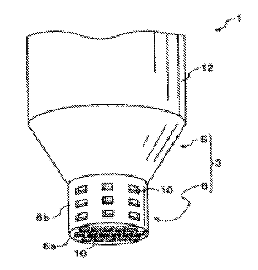
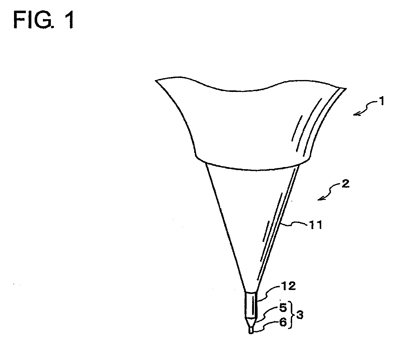
[0018]FIG. 1 is a perspective view showing parts of a press die using a punch according to a first embodiment of the invention. As shown in FIG. 1, the press die 1 includes a body portion 2, and a punch 3 formed at a lower end portion of the body portion 2 so as to be used for molding. The punch 3 of the press die 1 is used for molding a substrate 21 (see FIGS. 5A to 5C) of a nozzle plate. The body portion 2 has a conical portion 11 tapered off downwards, and a columnar portion 12 extending downwards from a lower end of the conical portion 11.

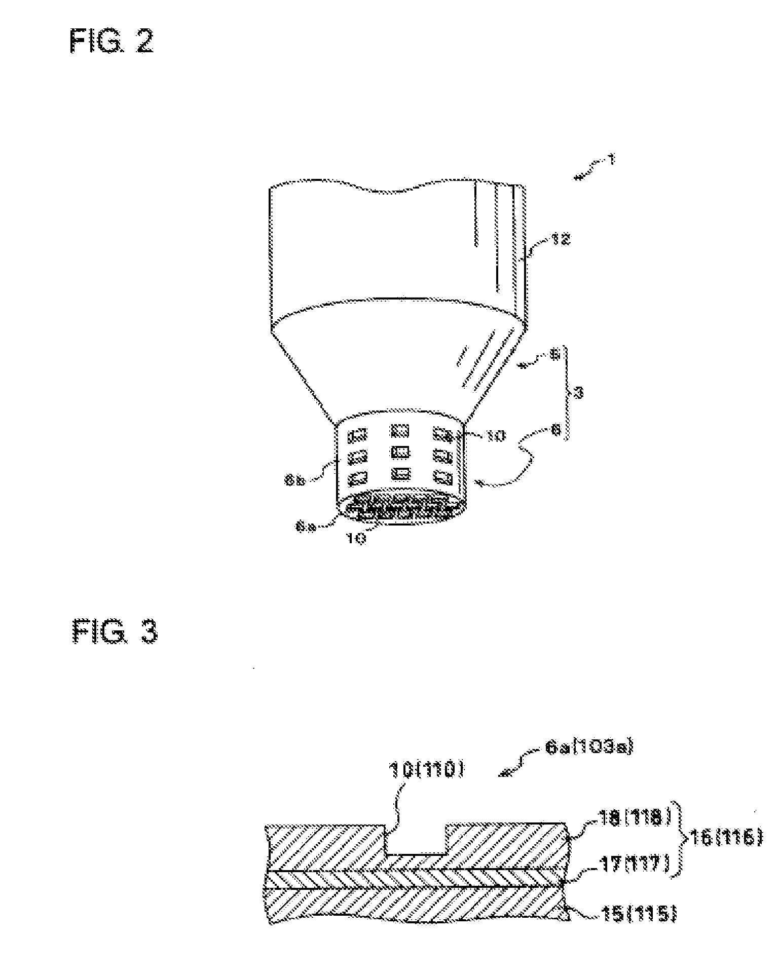
[0019]FIG. 2 is an enlarged perspective view of the punch 3 depicted in FIG. 1. As shown in FIG. 2, the punch 3, which is the end portion of ...


PUM

PropertyMeasurementUnit
mean particle sizeaaaaaaaaaa
particle sizeaaaaaaaaaa

Abstract

A punch for use in molding a workpiece with lubricating oil interposed between the punch and the workpiece includes a straight portion at its end and a diameter-increasing portion. The straight portion includes an end face at its end and a side face. The straight portion extends in an axial direction. The end surface extends in a radial direction perpendicular to the axial direction. The side surface is connected to the end surface. The diameter-increasing portion is connected to the straight portion. The diameter-increasing portion includes a width in the radial direction, which is identical to that of the straight portion, at a junction between the straight portion and the diameter-increasing portion. The width of the diameter-increasing portion in the radial direction increases with distance from the straight portion. At least one of the end surface and the side surface of the straight portion is formed with a pit.

Description

CROSS-REFERENCE TO RELATED APPLICATIONS[0001]This is a divisional application of U.S. patent application Ser. No. 11 / 390,352, which claims the benefit of priority from Japanese Patent Application No. 2005-94691 filed on Mar. 29, 2005, the disclosures of which are incorporated herein by reference.BACKGROUND OF THE INVENTION[0002]1. Field of the Invention[0003]The invention relates to a punch for use in molding a workpiece.[0004]2. Description of the Related Art[0005]Various molds and molding methods using the molds have been proposed in order to mold a workpiece. For example, JP S57-208250 A has disclosed a method of producing an inkjet nozzle from an orifice back sheet and an orifice sheet and a punch used in the method. This method of producing the inkjet nozzle is carried out as follows. A tip end portion of a conical punch is pressed against a sheet placed on a die to thereby form concave portions shaped in accordance with the shape of the tip end of the punch in the sheet. Then,...

Claims


Application Information

Patent Timeline
Patent Type & Authority Applications(United States)
IPC IPC(8): B21D37/18B21J3/00
CPCB23P15/16B26D7/088B26F1/14Y10T29/49837B41J2/1632B41J2/1637Y10T29/49833B41J2/162Y10T83/9423Y10T83/9428
Inventor ITO, ATSUSHINAKAMOTO, HIKARU
Owner BROTHER KOGYO KK
Learn More