Snubbing system for a suspended body

a suspension body and suspension technology, applied in the field ofinertial guidance, can solve problems such as damage or deformation, and achieve the effect of reducing the impact of shock

Inactive Publication Date: 2010-02-18
HONEYWELL INT INC
View PDF3 Cites 39 Cited by
  • Summary
  • Abstract
  • Description
  • Claims
  • Application Information

AI Technical Summary

Benefits of technology

[0004]The present invention generally relates to a snubbing or damping system for reducing a shock impact on an isolated body within a shock sensitive device, which may take the form of an inertial measurement unit (IMU). The shock sensitive device includes a housing with an inertial body suspended in an isolated manner within the housing and enga

Problems solved by technology

One result of this configuration is the sensitive component within the inertial sensor a

Method used


Image

  • Snubbing system for a suspended body
  • Snubbing system for a suspended body
  • Snubbing system for a suspended body

Examples


Embodiment Construction

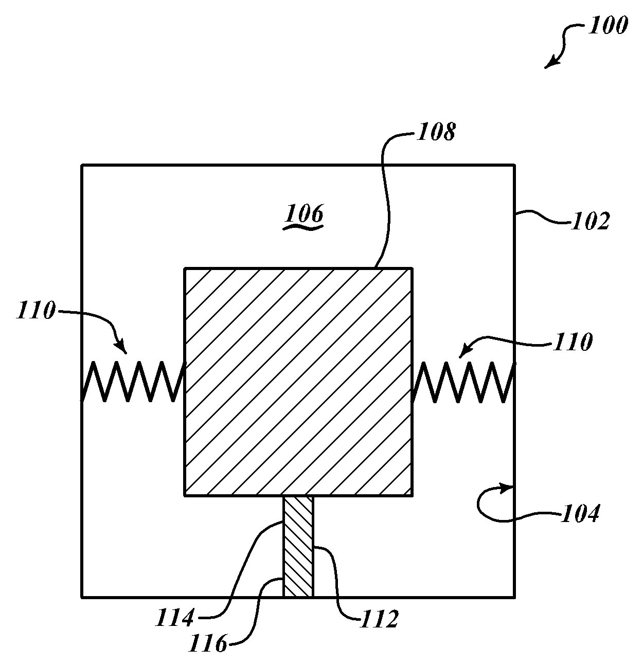
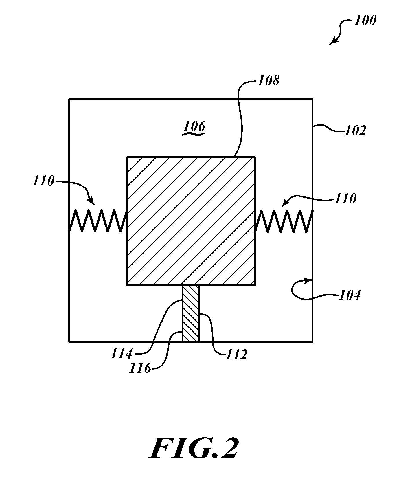
[0010]In one embodiment of the invention, an inertial snubbing system includes a housing having a housing wall defining an internal cavity and a body located within the internal cavity. In one embodiment, the body may take the form of an inertial sensor assembly for sensing a navigational direction. The system further includes a suspension system configured to isolatingly support the body within the cavity and with respect to the housing wall. In addition, a deformable snubbing mechanism is positioned between the body and the housing wall. The deformable snubbing mechanism includes a first end proximate the body and a second end proximate the housing wall such that the snubbing mechanism is arranged to be compressed substantially in a first direction during acceleration of the body in the first direction.

[0011]In another embodiment of the invention, an inertial measurement unit includes sensing means for sensing a navigational direction; support means for isolating the sensing means...


PUM


Abstract

The present invention generally relates to a snubbing or damping system for reducing a shock impact on an isolated body within a shock sensitive device, which may take the form of an inertial measurement unit (IMU). The shock sensitive device includes a housing with an inertial body suspended in an isolated manner within the housing and engaged with the snubbing system. By way of example, the inertial body may take the form of an inertial sensor assembly. Further, the snubbing system may take the form of a plastically deformable snubbing mechanism positioned between the housing and the inertial body along a line of action of the inertial body during an acceleration (e.g. shock) event.

Description

BACKGROUND OF THE INVENTION[0001]Inertial measurement units (IMUs) are used in a variety of applications. An IMU is the main component of inertial guidance systems used in air and space vehicles, watercraft vehicles, guided missiles and a variety of gun and artillery applications. IMUs work by detecting the current rate of acceleration, as well as changes in rotational attributes, including pitch, roll and yaw using a combination of accelerometers and gyroscopes. By way of example, the data collected from these sensors allows a computer to track a vehicle's position using a method known as dead reckoning. The term IMU commonly refers to a housing having an inertial sensor assembly, which may include three accelerometers and three gyroscopes comprising the assembly. The accelerometers and gyroscopes may be placed such that they can measure inertial acceleration, also known as G-forces. The accelerometers, for example, may be placed such that their measuring axes are orthogonal to eac...

Claims


Application Information

Patent Timeline
IPC IPC(8): G01P3/00F16F9/30
CPCF16F15/046
Inventor GROSSMAN, OWEN
Owner HONEYWELL INT INC
Why Eureka
Try Eureka