System for reducing deposits on a compressor

Active Publication Date: 2010-02-18
GENERAL ELECTRIC CO
View PDF24 Cites 27 Cited by
  • Summary
  • Abstract
  • Description
  • Claims
  • Application Information

AI Technical Summary

Benefits of technology

[0006]In an embodiment of the present invention, a water wash system for a turbomachine comprising an inlet plenum and a compressor, the water wash system comprising: a plurality of nozzles positioned within the inlet plenum; a first tank for storing a cleaning fluid used by the water wash system; and a second tank for storing at least one chemical agent used by the water wash system; wherein the water wash system mixes the at least one chemical agent with the cleaning fluid to create at least one cleaning solution which is moved through the plurality of nozzles towards the compressor; and wherein the cleaning solution can reduce a level of corrosives on the compressor.
[0007]In an alternate embodiment of the present invention, a system for reducing the corrosives on a compressor of a turbomachine, the system comprising: an inlet system for directing air into the compressor of the turbomachine, the inlet system comprising: an inlet filter house for screening an airstream entering the inlet system; a cooling module for conditioning the airstream within the inlet system; a silencer section for reducing noise within the inlet system; an inlet bleed heat system for conditioning the airstream; and an inlet plenum; and a water wash system comprising: a plurality of nozzles positioned within the inlet plenum; a first tank for storing at least one cleaning fluid used by the water wash system; and a second tank for storing at least one chemical agent used by the water wash system; wherein the water wash system mixes the at least one chemical agent with the cleaning fluid to create a cleaning solution, and pumps the cleaning solution through the plurality of nozzles towards the compressor; and wherein the cleaning solution can reduce corrosives on the compressor.

Problems solved by technology

These microenvironments, which have accelerated airflows and pressures, typically increase the corrosion rate of the components of the compressor.

Method used


Image

  • System for reducing deposits on a compressor
  • System for reducing deposits on a compressor
  • System for reducing deposits on a compressor

Examples


first embodiment

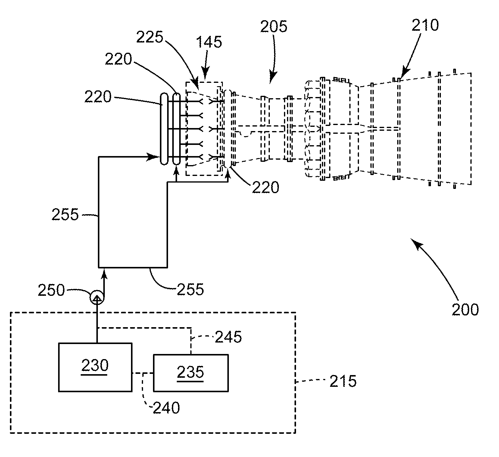
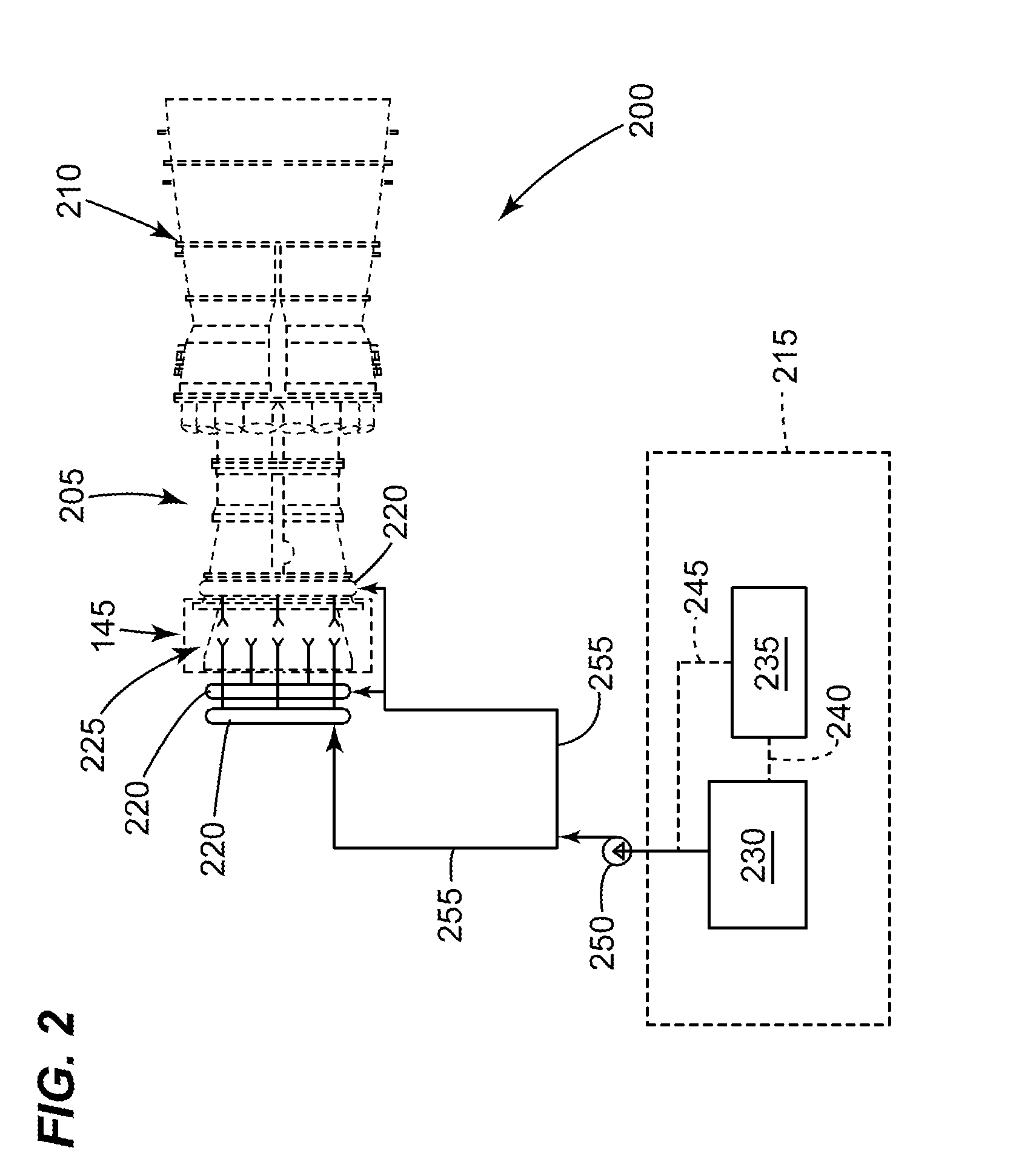
[0020]the water wash system 215 may comprise: at least one manifold 220 each of which having nozzles 225 attached. A first tank 230 for housing a cleaning fluid, such as, but not limiting of, de-min water; a second tank 235 for storing a chemical agent, such as, but not limiting of, an acidic agent or a basic agent. A direct line 240 allows the contents of the second tank 235 to enter the first tank 230. At least one pump 250 for moving the contents of the first tank 230 and the second tank 235 through the nozzles 225.

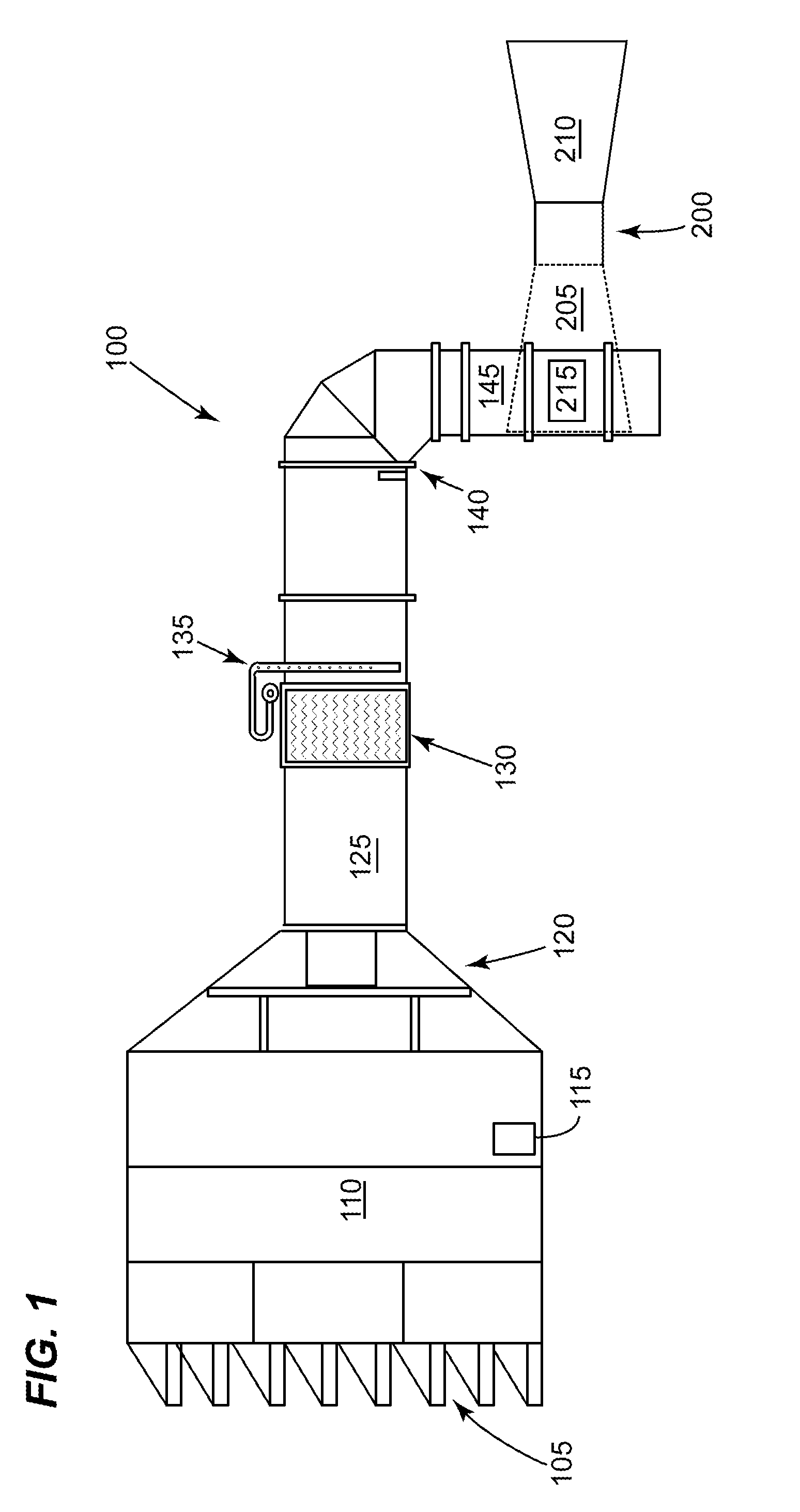
[0021]The environment that the turbomachine 200 operates may allow for corrosive elements, ingested by the inlet system 100, to deposit of the blades of the compressor 205. These deposits may be either sold or liquid in nature. As the humidity of the airstream increases, the solid deposits, such as, but not limiting of, salts, may absorb moisture from and liquefy, as an acid or base. and cause corrosion on the parts of the compressor 205.

[0022]Generally, if the operati...

second embodiment

[0029]An operator using this second embodiment of the present invention may have determined that corrosive deposits foul the compressor 205. The operator may configure the water wash system 215 to allow for a predetermined amount of the at least one chemical agent in the second tank 235 to enter the header 255 via the bypass line 245. The operator may utilize a mixer, vibration means, or the like (not illustrated in FIG. 2) to mix the at least one chemical agent with the cleaning fluid of the first tank 230, creating the cleaning solution. Next the pump 250 may be operated to move the cleaning solution to the manifold(s) 220. The pump 250 may then drive the cleaning solution through the spray nozzles 225 where the cleaning of the compressor 205 commences. The duration that the water wash system 215 operates generally depends on the nature and severity of the corrosion on the components of the compressor 205.


PUM


Abstract

An embodiment of the present invention provides a water wash system that may mix a cleaning fluid with at least one chemical agent to form a cleaning solution. The cleaning solution may reduce the corrosives on components of a compressor. The cleaning solution may be an mildly acidic solution to reduce corrosion of a caustic nature. Alternatively, the cleaning solution may be a mildly basic solution to reduce corrosion of an acidic nature.

Description

BACKGROUND OF THE INVENTION[0001]The present invention relates generally to a turbomachine; and more particularly to a water wash system for cleaning the compressor of a turbomachine.[0002]Some turbomachines, such as, but not limiting of, gas turbines, and aero-derivatives, have an air inlet system that channels the incoming airstream towards a compressor. The inlet system usually has a filter section, which screens the airstream of foreign objects and other undesired materials. Typically, the inlet system and the compressor are created out of metals that may corrode due to the environment (ambient conditions, etc) in which the turbomachine operates. These turbomachines may develop microenvironments related to the ambient conditions in which the turbomachine operates. These microenvironments, which have accelerated airflows and pressures, typically increase the corrosion rate of the components of the compressor.[0003]Water wash systems are commonly used to remove the contaminants an...

Claims


Application Information

Patent Timeline
IPC IPC(8): B08B13/00
CPCF01D25/002F01D25/007F02C3/30F05D2260/212F05D2270/08F05D2260/95F04D29/705
Inventor GEBHARDT, ERICCHILLAR, RAHUL J.DAVIS, DALE J.
Owner GENERAL ELECTRIC CO
Why Eureka
Try Eureka