Ink degassing for circulating ink supply systems in ink jet printers

a technology of ink jet printers and ink supply systems, which is applied in printing and other directions, can solve the problems of insufficient pressure to form a continuous stream of ink drops, limited, and less suitable as process variables, and achieve the effect of guarantying the quality of degassed ink delivered

Active Publication Date: 2010-02-18
AGFA NV
View PDF8 Cites 45 Cited by
  • Summary
  • Abstract
  • Description
  • Claims
  • Application Information

AI Technical Summary

Benefits of technology

[0010]In view of the problems described above, preferred embodiments of the present invention improve the ink circulation and inline degassing concepts known in the art for use with an ink jet printing apparatus, and to better guarantee the quality of the degassed ink delivered to ink jet print heads.
[0013]A major advantage of the ink circulation system according to a preferred embodiment of the invention is that the ink flow rate through the degassing unit can be controlled independently from the ink flow rate through the ink jet print head, so as to provide optimal operating conditions for the through-flow degassing unit.
[0014]Another advantageous effect of the ink circulation system according to a preferred embodiment of the invention is that ink is degassed at the location of the intermediate storage just before being supplied to the ink jet print head.

Problems solved by technology

The ink supply is not sufficiently pressurized to form a continuous stream of ink drops.
A hydrostatic pressure difference is, from a practical point of view, always limited and less suitable as a process variable to control an ink flow rate.
Therefore the ink flow rate in the ink circulation system is limited in size and limited in controllability.
The technical problem of the prior art ink circulation and degassing system is that the main ink circulation path taps degassed ink from the shortcut degassing circuit, via controllable valves, at a low flow rate and stores the tapped ink in an intermediate storage tank before being used by the print head.

Method used


Image

  • Ink degassing for circulating ink supply systems in ink jet printers
  • Ink degassing for circulating ink supply systems in ink jet printers
  • Ink degassing for circulating ink supply systems in ink jet printers

Examples


Embodiment Construction

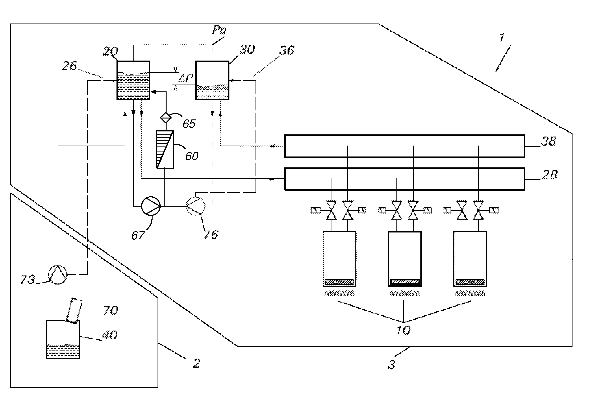
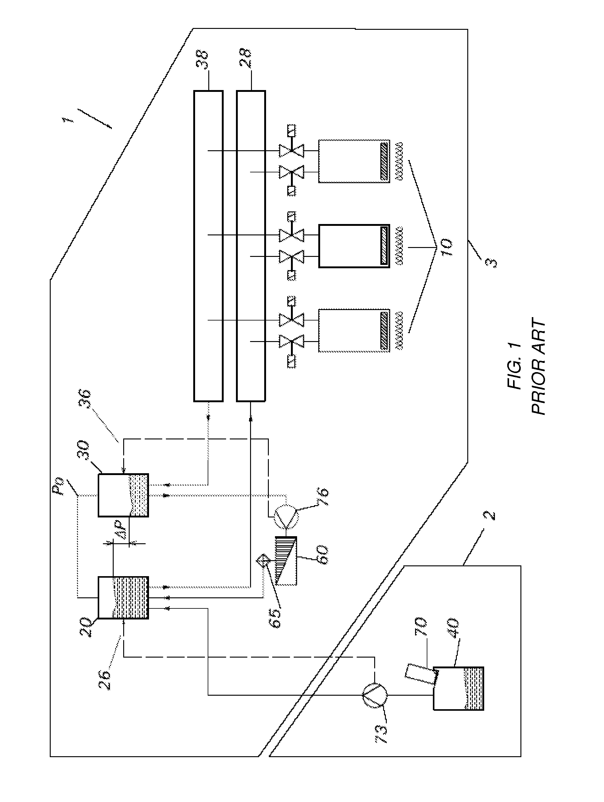
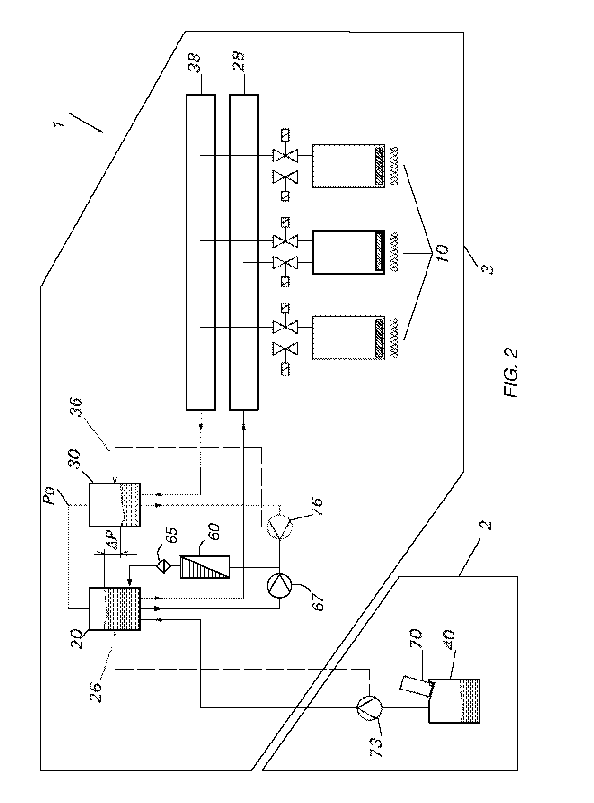
[0019]With reference to FIG. 1, an ink circulation system with inline degassing unit is described as known from the prior art. The system includes an ink supply subtank 20 for providing ink to a set of ink jet print heads 10, and an ink return subtank 30 for returning the ink not used for printing from the set of ink jet print heads 10. The supply subtank 20 and return subtank 30 are equipped with ink level sensor 26 and ink level sensor 36, respectively. Preferred embodiments of the level sensors 26 and 36 may include an ultrasonic level sensor with a switching output or analogue output as available from Hans Turck GmbH & Co (DE). The level sensors 26 and 36 may also include a set of Hall detectors arranged at the outside of the subtank, along a vertical wall, the Hall detectors being associated with a floating member having a magnet attached thereto, arranged inside the subtank. The number of Hall detectors in the set determines the degree of binary versus continuous measurement. ...


PUM


Abstract

An ink circulation system includes a supply subtank for supplying ink to an ink jet print head and a return subtank returning the ink not ejected by the ink jet print head. A print circulation path links the supply subtank with the ink jet print head and the return subtank for providing a print flow of ink from the supply subtank to the ink jet print head, the return subtank, and back to the supply subtank. A degas circulation path links the supply subtank with a through-flow degassing unit for providing a degas flow of ink from the supply subtank to the through-flow degassing unit and back to the supply subtank. The ink circulation system improves the degassing quality of the ink supplied to the ink jet print head of a printing apparatus is provided.

Description

CROSS-REFERENCE TO RELATED APPLICATIONS[0001]This application is a 371 National Stage Application of PCT / EP2007 / 064415, filed Dec. 21, 2007. This application claims the benefit of U.S. Provisional Application No. 60 / 880,908, filed Jan. 17, 2007, which is incorporated by reference herein in its entirety. In addition, this application claims the benefit of European Application No. 06127283.7, filed Dec. 28, 2006, which is also incorporated by reference herein in its entirety.BACKGROUND OF THE INVENTION[0002]1. Field of the Invention[0003]The present invention relates to a droplet deposition apparatus. More specifically, the invention relates to circulating ink supply systems for use with the ink jet printing apparatus.[0004]2. Description of the Related Art[0005]Ink jet printing technology, due to its sheer simplicity (and its ability to dispense very small controlled droplets of ink) has found a great audience. Brochures, advertisement, fliers, business cards, labels are some applica...

Claims


Application Information

Patent Timeline
Patent Type & Authority Applications(United States)
IPC IPC(8): B41J2/19
CPCB41J2/175B41J2/19
Inventor WOUTERS, PAULVAN DE WYNCKEL, WERNER
Owner AGFA NV
Why Eureka
Try Eureka