Cycle modulation circuit for limiting peak voltage

a technology of peak voltage and cycle modulation circuit, which is applied in the direction of dc-dc conversion, power conversion system, electrical apparatus, etc., can solve the problems of peripheral devices and semiconductor elements at the rear end that cannot be started, damage to equipment, and damage to equipmen

Active Publication Date: 2010-02-18
SPI ELECTRONICS
View PDF3 Cites 15 Cited by
  • Summary
  • Abstract
  • Description
  • Claims
  • Application Information

AI Technical Summary

Benefits of technology

[0006]Therefore, the primary object of the present invention is to limit the controllable maximum

Problems solved by technology

Without this equipment cannot be started normally, and unpredictable voltage and current surges could take place to cause damage of the equipment.
If the peak-to-peak value (Vpp) of the driving power generated by the power driving unit cannot be properly controlled or output error is excessive, the peripheral devices and semiconductor elements at the rear end could be damaged.
As a result, the cost is higher.
Hence controlling the peak-to-peak value (Vpp) of the driving power is an important research issue of power supply.
In practice, these elements have different characteristics and cannot be totally the same even made with same specifications.
As a result, the oscillators are not as accurate as desired and do not fully con

Method used


Image

  • Cycle modulation circuit for limiting peak voltage
  • Cycle modulation circuit for limiting peak voltage
  • Cycle modulation circuit for limiting peak voltage

Examples


Embodiment Construction

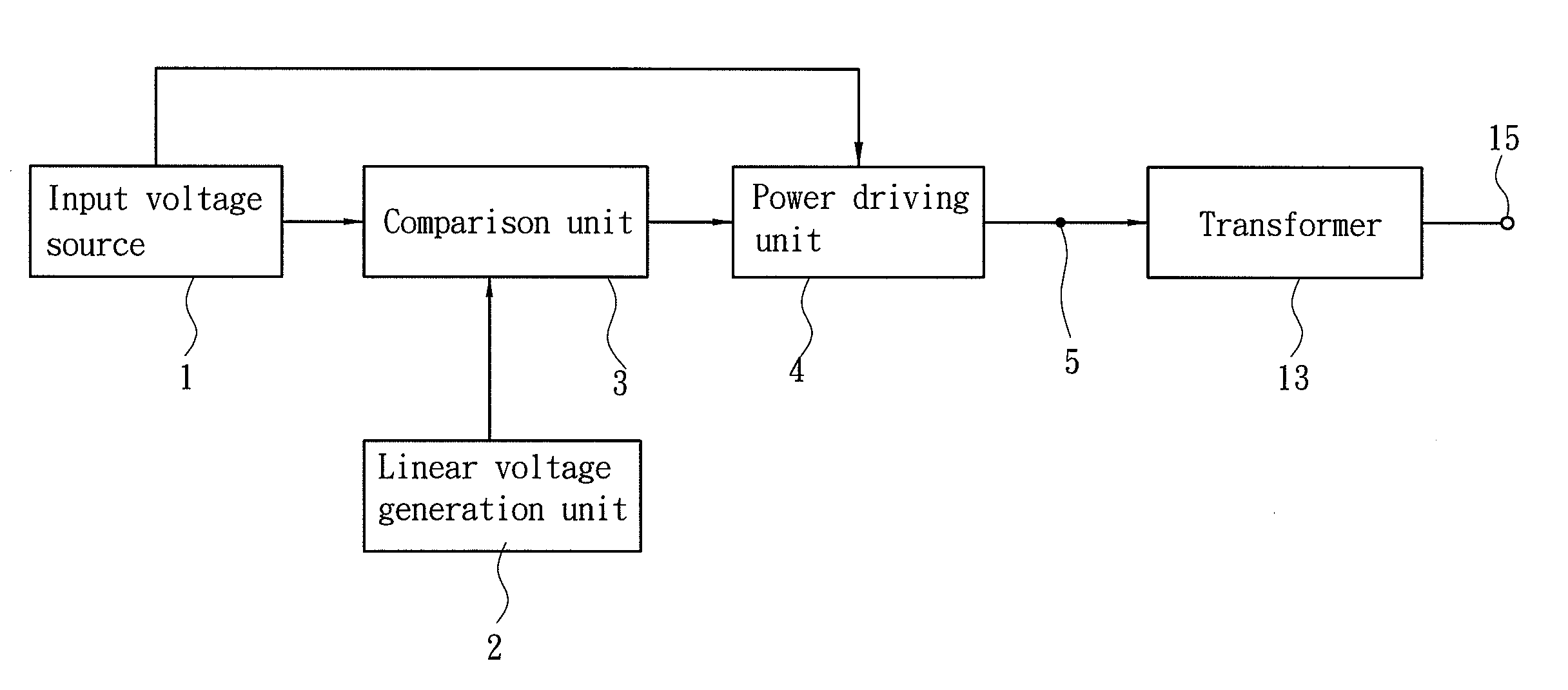
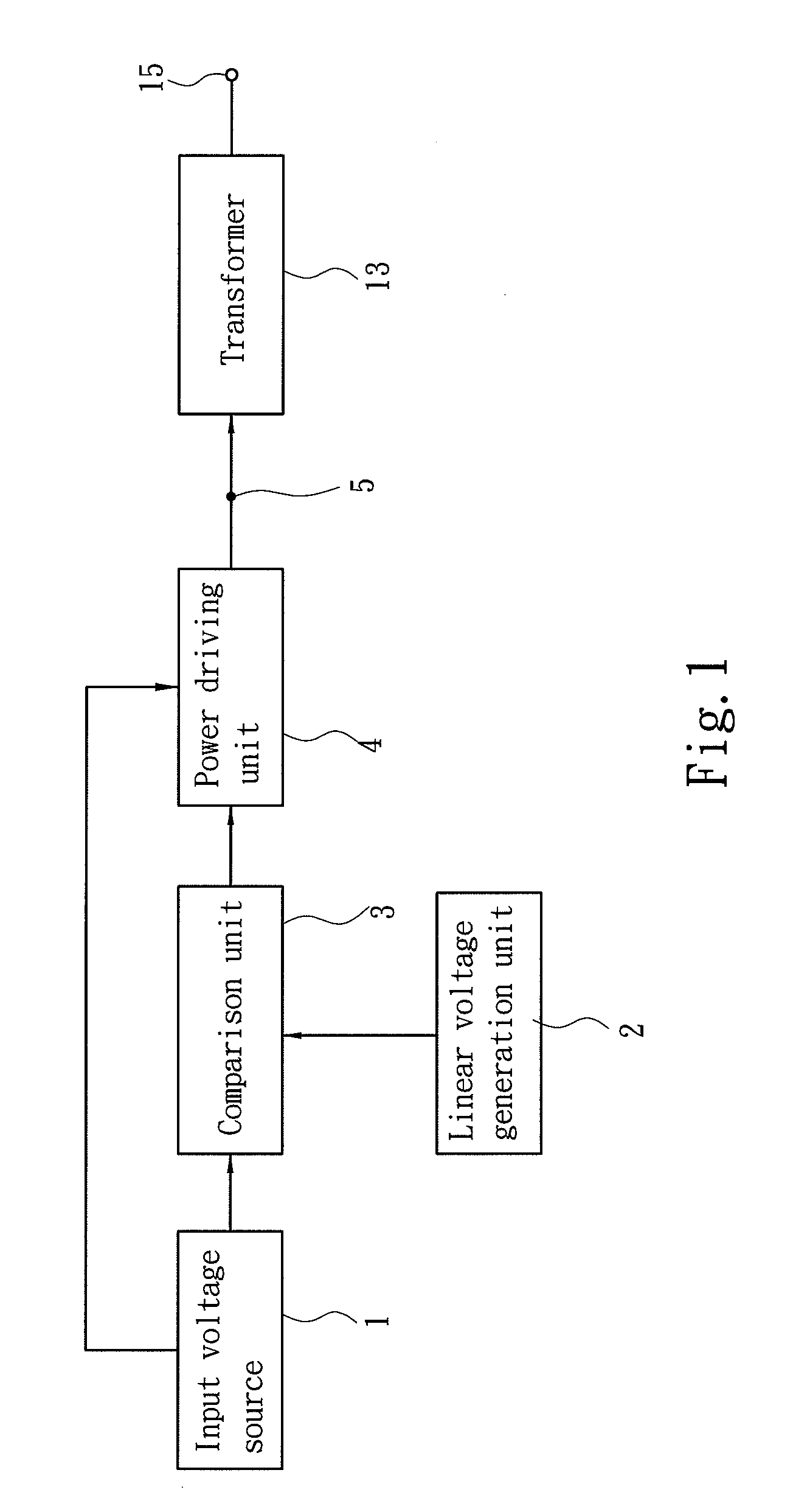
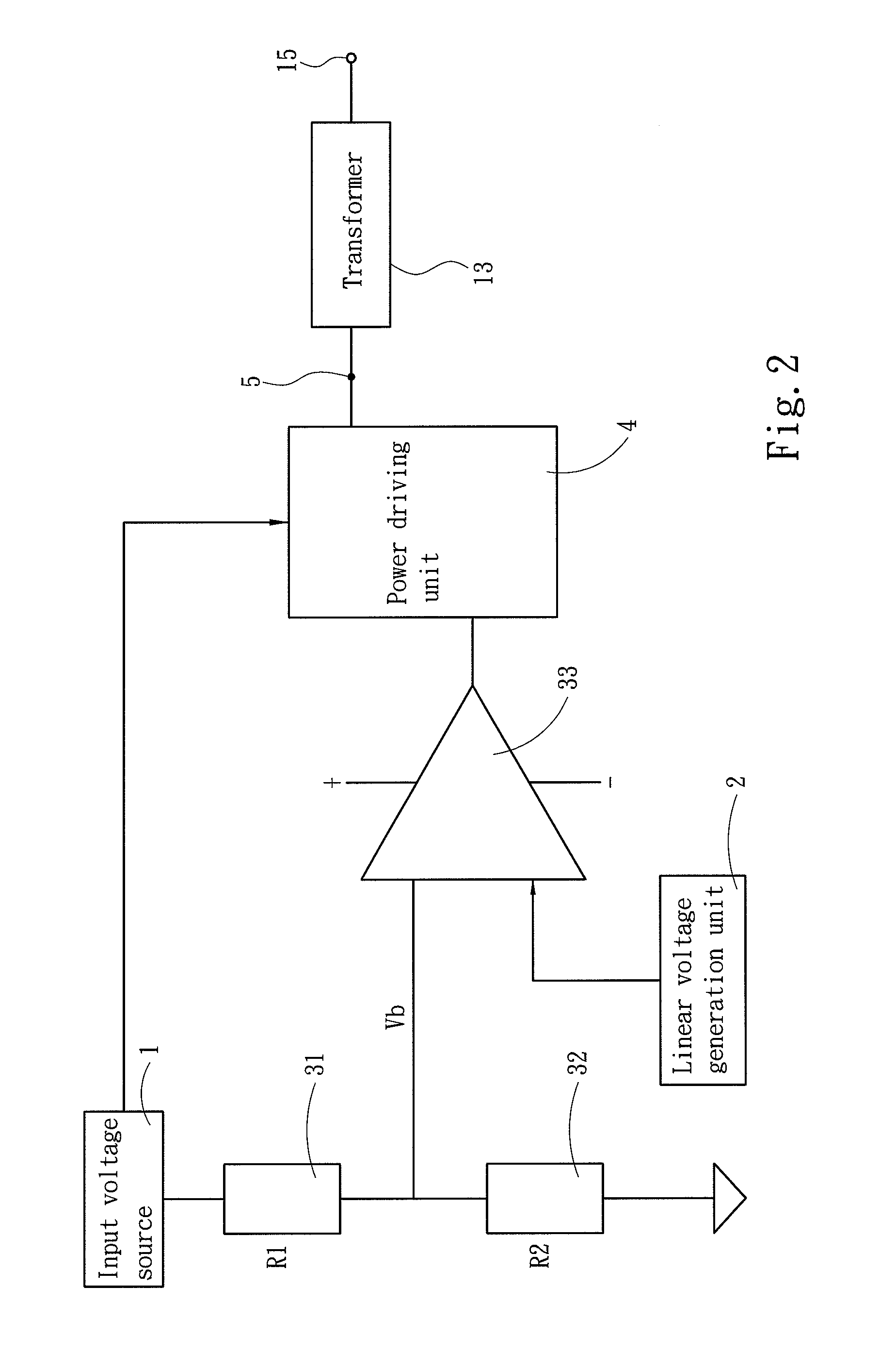
[0015]Please refer to FIGS. 1 through 6, the present invention provides a cycle modulation circuit to limit allowable maximum duty cycle of a power driving unit to limit peak-to-peak value of driving power.

[0016]FIGS. 1 and 6 illustrate an embodiment of the invention adopted for use on a power supply. The power supply has a power driving unit 4 receive an input power from an input voltage source 1. The power driving unit 4 includes a pulse width modulation (PWM) circuit 41 which outputs a PWM signal to drive an active clamp. The active clamp has at least two switches 421 and 422 operating in opposite phases. To show the switches 421 and 422 operating in an opposite manner, an inverter 423 is added on the path of the switch 422 driven by the PWM signal. However, using the switches 421 and 422 is not the limitation of the invention to establish the opposite operation as long as the switches 421 and 422 do offer opposite operation and conform to active clamp operation mode. The active ...


PUM


Abstract

A cycle modulation circuit for limiting voltage peak value of a power supply employed an active clamp. The power supply receives an input power which is modulated through a power driving unit to become a driving power transformed through a transformer to be output. The cycle modulation circuit includes a comparison unit and a linear voltage generation unit. The comparison unit receives the input power to generate a level signal which is used as a base value to compare level with an oscillation signal generated by the linear voltage generation unit, thereby to modulate and output a pulse width limit signal with a composite cycle consisting of a high level and a low level. The pulse width limit signal is input to the power driving unit to limit the peak value of the driving power modulated by the power driving unit.

Description

[0001]This application is a continuation-in-part, and claims priority, of from U.S. patent application Ser. No. 11 / 599,290 filed on Nov. 15, 2006, entitled “CYCLE MODULATION CIRCUIT CAPABLE OF LIMITING PEAK VOLTAGE”.FIELD OF THE INVENTION[0002]The present invention relates to a cycle modulation circuit for limiting peak voltage and particularly to a cycle modulation circuit that uses a level signal generated by an input voltage source as a base value to compare with an oscillation signal generated by a linear voltage generation unit to produce a pulse width limit signal to limit the peak value of driving power.BACKGROUND OF THE INVENTION[0003]Power supply is an indispensable element on many information products. Its most important mission is to provide sufficient and stable voltage. Without this equipment cannot be started normally, and unpredictable voltage and current surges could take place to cause damage of the equipment.[0004]The conventional power supply controls the duty cyc...

Claims


Application Information

Patent Timeline
IPC IPC(8): H02H7/122
CPCH02M3/156H03K7/08H02M2001/0016H02M3/33507H02M1/0016
Inventor LIN, KUO-FAN
Owner SPI ELECTRONICS
Why Eureka
Try Eureka