Novel peak detection circuit

A peak detection circuit and a new type of technology, applied in the direction of AC/pulse peak measurement, etc., can solve the problems of inconsistent linearity of the circuit, the overall complexity of the circuit, the power consumption and the occupied area, etc., to reduce the circuit area and reduce the power consumption. consumption, and the effect of improving linearity

Active Publication Date: 2019-04-16
UNIV OF ELECTRONICS SCI & TECH OF CHINA
View PDF6 Cites 0 Cited by
  • Summary
  • Abstract
  • Description
  • Claims
  • Application Information

AI Technical Summary

Problems solved by technology

[0004] 1. Since the diode is the core component of this type of peak protection circuit, the characteristics of the circuit at high temperature and normal temperature will change due to the temperature characteristics of the diode, resulting in inconsistent linearity of the circuit at high temperature and n

Method used


Image

  • Novel peak detection circuit
  • Novel peak detection circuit
  • Novel peak detection circuit

Examples


Embodiment

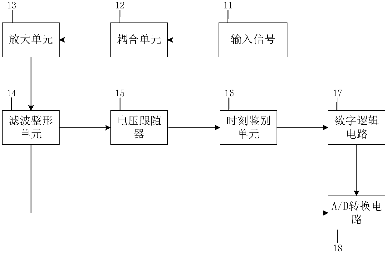
[0028] figure 1 It is a novel peak detection circuit diagram of the present invention;

[0029] In this example, if figure 1 As shown, a novel peak detection circuit of the present invention includes: an input signal unit 11, a coupling unit 12, an amplification unit 13, a filter shaping unit 14, a voltage follower 15, a time discrimination unit 16, a digital logic circuit 17 and an A / D Conversion circuit 18

[0030] The input signal unit 11 provides the input signal for the novel peak detection circuit; in the present embodiment, as Figure 5 As shown in (a), the input signal is a triangle wave with a pulse width of 2 microseconds and an amplitude of 0 to 4.5 volts;

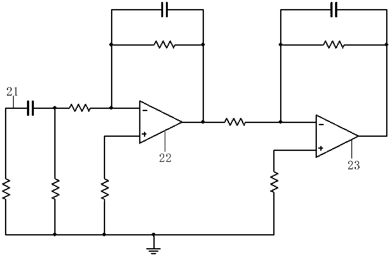
[0031] coupling unit 12, such as figure 2 As shown, an RC coupling circuit 21 is used; in the RC coupling circuit 21, one end of the capacitor is connected to the input signal, and the other end is the output end of the coupling unit 12; one end of the resistor is grounded, and the other end is connected to...


PUM


Abstract

The invention discloses a novel peak detection circuit. The novel peak detection circuit mainly comprises a coupling unit, an amplifying unit, a filtering and shaping unit, a voltage follower, a timediscrimination unit, an A/D conversion circuit and a digital logic circuit; the coupling unit couples the input pulses, so that a relatively gentle negative peak is generated; and the waveform is subjected to shaping and gain adjustment of the amplification unit; the processed waveform is further broadened and amplified through the filtering and shaping unit; two paths of signals are outputted, wherein one of the two paths of signals is inputted to the voltage follower, and the other path is inputted to the A/D conversion circuit; the voltage follower buffers the signals, and then inputs the buffered signals to the time identification unit; the time identification unit performs time identification on the waveform, eliminates time discrimination deviation and inputs the processed waveform to the digital logic circuit; and the digital logic circuit calculates the peak arrival time of the output waveform of the filtering and shaping unit and controls the A/D conversion circuit to acquirea pulse peak at appropriate time.

Description

technical field [0001] The invention belongs to the technical field of peak detection, and more specifically relates to a novel peak detection circuit. Background technique [0002] In the process of density logging while drilling, it is necessary to collect the peak value of the input pulse, and the duration of the peak value of the pulse is usually very short, so it is necessary to use a circuit to change the shape of the input pulse, so that the A / D conversion circuit has sufficient The conversion time of the peak value is collected. The peak hold circuit is often used to hold the peak value of the input signal, which is generally realized by using the unidirectional conductivity of the diode and the storage charge function of the capacitor, mainly including operational amplifiers, diodes, capacitors, buffers, switches, oscillators, comparisons device. The principle is that the input signal is input to the non-inverting terminal of the operational amplifier, and the out...

Claims


Application Information

Patent Timeline
IPC IPC(8): G01R19/04
CPCG01R19/04
Inventor 李焱骏董海涵师奕兵张伟
Owner UNIV OF ELECTRONICS SCI & TECH OF CHINA
Why Eureka
Try Eureka