Optical member manufacturing method, optical member manufacturing apparatus and optical member
- Summary
- Abstract
- Description
- Claims
- Application Information
AI Technical Summary
Benefits of technology
Problems solved by technology
Method used
Image
Examples
first embodiment
[0071]First, a first embodiment of an optical member manufacturing method according to the invention will be described.
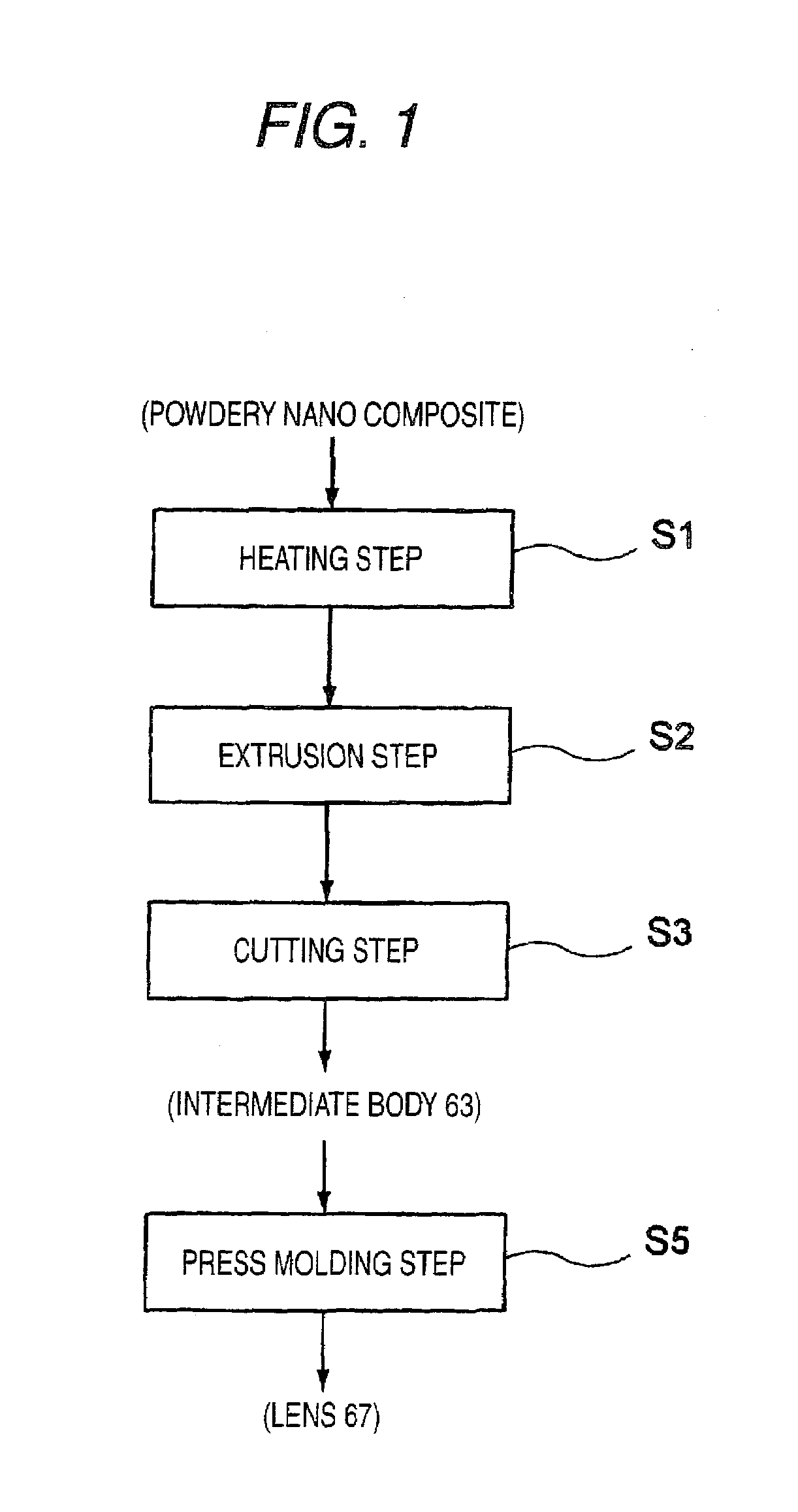
[0072]FIG. 1 is a flowchart showing a schematic procedure of the optical member manufacturing method according to the first embodiment of the invention.
[0073]As shown in FIG. 1, a nano composite powder is formed into an agglomerate intermediate body 63, by an intermediate body forming apparatus which will be described later, through a heating step (step 1: S1), an extrusion step (S2), and a cutting step (S3). Next, the intermediate body 63 is heated and compressed by press-molding (S4), whereby an optical member 67 such as a lens is manufactured. The nano composite powder is material in which inorganic fine particles each having average particle size of from 1 to 15 nm are dispersed in a thermoplastic resin, of which the detail will be described later.
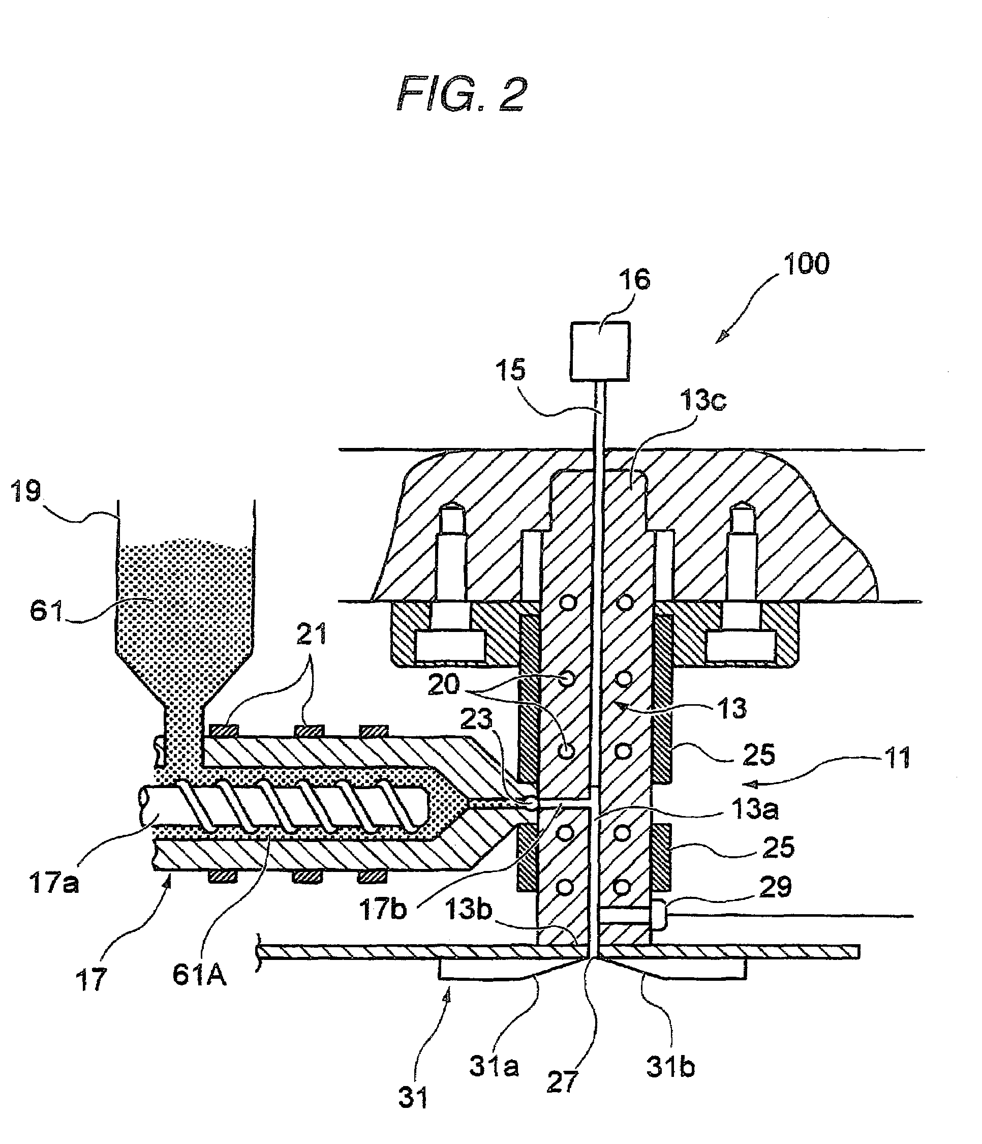
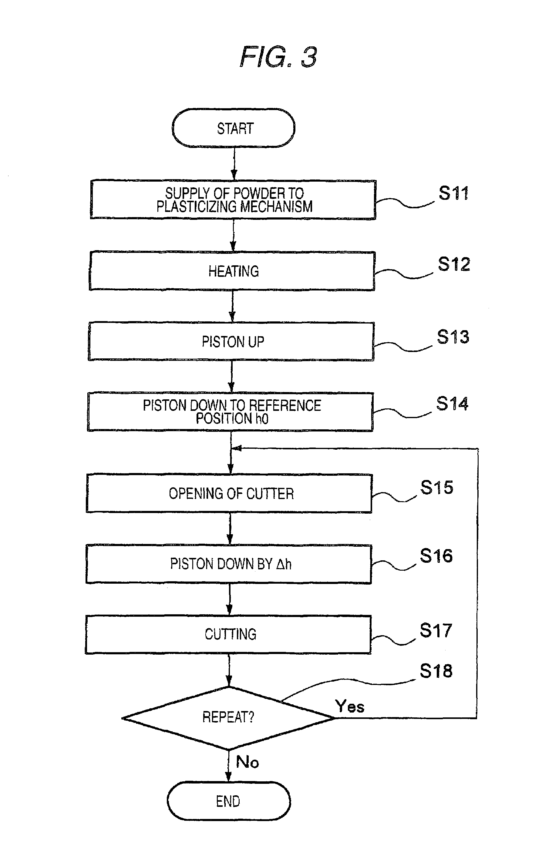
[0074]The above steps will be described below in order. First, the heating step S1, the extrusion step S2, and the c...
second embodiment
[0105]Next, a second embodiment of the optical member manufacturing method according to the invention will be described with reference to FIGS. 6 to 8.
[0106]FIG. 6 is a flowchart showing a schematic procedure of the optical member manufacturing method according to the second embodiment of the invention, FIG. 7 is an explanatory view showing a step of molding a preform by heat-compressing an agglomerate intermediate body, and FIG. 8 is an explanatory view showing a step of molding an optical member from the preform by a compression-molding apparatus (press-molding apparatus).
[0107]In the optical member manufacturing method in the embodiment, as shown in FIG. 6, through a heating step (S1), an extrusion step (S2), and a cutting step (S3) which are similar to those in the first embodiment, an agglomerate intermediate body is formed. Next, the intermediate body is compressed in a compression step S5 thereby to be molded into a preform having the shape close to the shape of an optical me...
third embodiment
[0114]Next, a third embodiment of the optical member manufacturing method according to the invention will be described with reference to FIGS. 9 and 10.
[0115]FIG. 9 is a flowchart showing a schematic procedure of an optical member manufacturing method in the third embodiment, and FIG. 10 is an explanatory view showing a step of molding a preform directly from a nano composite powder by heat-compressing the nano composite powder.
[0116]In the schematic manufacturing method of the optical member in this embodiment, as shown in FIG. 9, a nano composite powder is put in a preform molding apparatus as it is, and molded into a preform having the shape close to the shape of a lens (optical member) through a heating step (S7) and a compression step (S8). Next, in a press molding step (S9) similar to that in the second embodiment, an optical ember that is a finished product is manufactured. This embodiment is different from the second embodiment in the preform molding method.
[0117]As shown in...
PUM
| Property | Measurement | Unit |
|---|---|---|
| Particle diameter | aaaaa | aaaaa |
| Volume | aaaaa | aaaaa |
| Shape | aaaaa | aaaaa |
Abstract
Description
Claims
Application Information
 - R&D
- Intellectual Property
- Life Sciences
- Materials
- Tech Scout
- Unparalleled Data Quality
- Higher Quality Content
- 60% Fewer Hallucinations
Browse by: Latest US Patents, China's latest patents, Technical Efficacy Thesaurus, Application Domain, Technology Topic, Popular Technical Reports.
© 2025 PatSnap. All rights reserved.Legal|Privacy policy|Modern Slavery Act Transparency Statement|Sitemap|About US| Contact US: help@patsnap.com


