Method for producing tire vulcanizing mold and tire vulcanizing mold

Active Publication Date: 2006-11-16
BRIDGESTONE CORP
View PDF8 Cites 20 Cited by
  • Summary
  • Abstract
  • Description
  • Claims
  • Application Information

AI Technical Summary

Benefits of technology

[0016] According to a first aspect of the present invention, there is provided a process for manufacturing a tire vulcanizing mold, comprising making at least part of a mold element for a tire tread portion out of a sintered member and a mold element f

Problems solved by technology

In the method in which the air vent or exhaust passage is formed, as the above air vent or the exhaust passage is small in size and a surface projection having a complex shape is existent therearound, it is difficult to form a hole or pore having a desired diameter.
For example, in the case of milling, as the width of a slit to be formed is very small, the cutter strength and the processing depth are limited and the processing time becomes very long.
In the case of discharge processing, the manufacture of an electrode is necessary, and the processing depth is limited due to limitations such as the removal of cutting powders and the curvature of the electrode.
Laser beam processing making use of a laser such as CO2 laser or YAG laser is conceivable but the processing depth is limited due to the focusing distance of a laser beam when the width of a groove is 0.1 mm or less.
Since the size of the above air vent or the exhaust passage is limited by a tool in use, a very small hole or pore cannot be formed with high accuracy.
As a result, a rubber material which becomes a fluid by vulcanizing heat at the time of molding a

Method used


Image

  • Method for producing tire vulcanizing mold and tire vulcanizing mold
  • Method for producing tire vulcanizing mold and tire vulcanizing mold
  • Method for producing tire vulcanizing mold and tire vulcanizing mold

Examples


embodiment 1

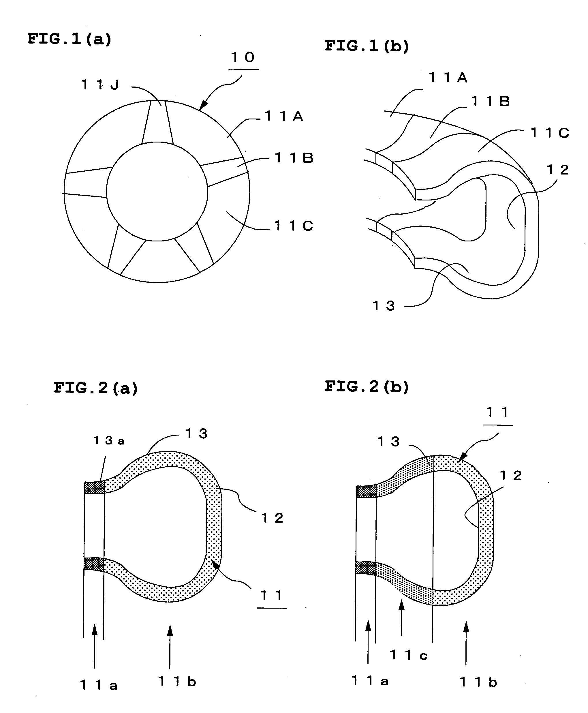
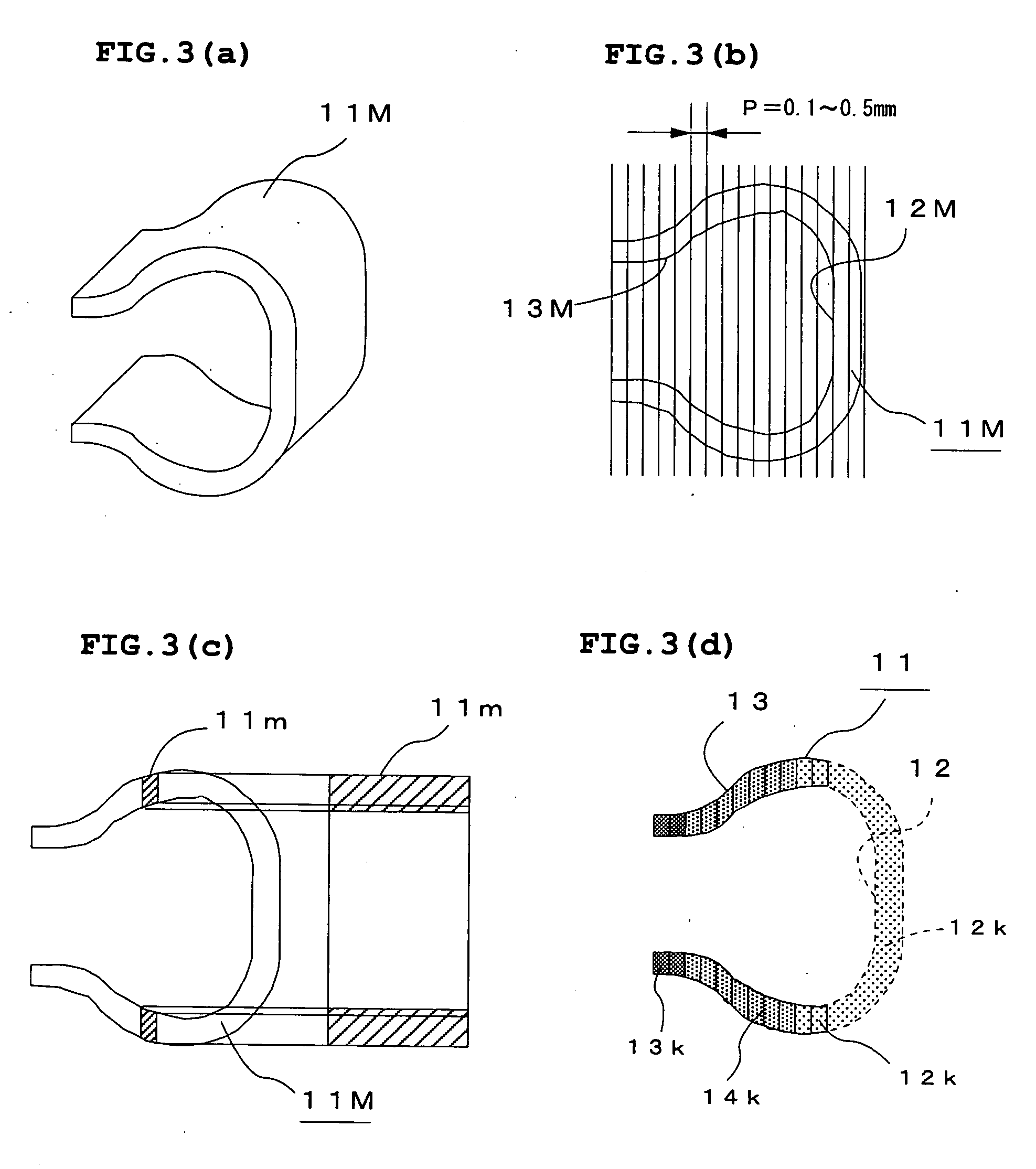
[0062] FIGS. 1 (a) and 1 (b) show the constitution of a tire vulcanizing mold 10 according to this embodiment. This tire vulcanizing mold 10 is a split type mold consisting of a plurality of sector molds 11 (11A to 11J) which are interconnected in a loop. In this embodiment, a crown portion 12 having the sectional form of a tire crown portion and side portions 13 in contact with side tread portions are formed integrally on the tire side (inner side) of the above sector mold 11 by the above-described powder sintering method. Powders are sintered by changing heating and sintering conditions so that a portion including the crown portion 12 which does not require strength but has a complex structure is made a sparse portion 11b having a low density (therefore, having a lot of pores) of a sintered body and portions 13a corresponding to the mating portions of the mold of the side portions 13 (to be referred to as “mating portions” hereinafter), which require strength, are made dense porti...

embodiment 2

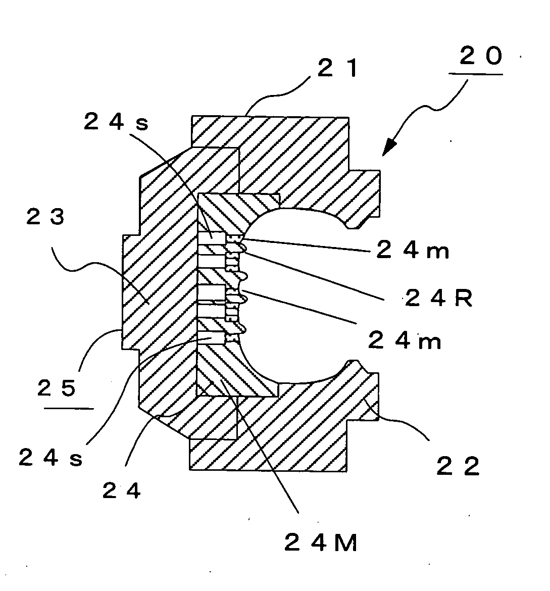
[0077] FIGS. 6(a) and 6(b) show the constitution of a tire vulcanizing mold 20 according to Embodiment 2. This mold 20 consists of a plurality of sector molds 25, each consisting of upper and lower molds 21 and 22 in contact with tire side portions and a plurality of vulcanizing mold pieces (to be referred to as “pieces” hereinafter) 24 fixed to a holder 23, arranged in a loop in the circumferential direction of a tire. A tread marking surface 24a (portion exposed to the inner wall of the mold 20) which is a recessed portion of each piece 24 is a tire forming surface, that is, a portion to be in close contact with green tire rubber to be vulcanized.

[0078] The tire forming surface 24a of each piece 24 has projections (to be referred to as “rib portions” hereinafter) 24R corresponding to a vertical groove pattern and projections (to be referred to as “lug portions” hereinafter) 24L corresponding to a horizontal groove pattern (lug pattern) of a tire tread as shown in FIG. 7. In this ...

embodiment 3

[0086]FIG. 8(a) and 8(b) show the constitution of a tire vulcanizing mold 30 according to this Embodiment 3. This mold 30 consists of a plurality of sector molds 35, each consisting of upper and lower molds 31 and 32 in contact with tire side portions and a plurality of pieces 34 fixed to a holder 33, arranged in a loop in the circumferential direction of a tire. The tread marking surface (portion exposed to the inner wall of the mold 30) 34a which is a recessed portion of each piece 34 is a tire forming surface, that is, a portion to be in close contact with green tire rubber to be vulcanized.

[0087] As show in FIG. 9, a plurality of slits 37 for discharging a gas generated at the time of vulcanizing a tire to the outside of the mold are formed in the above piece 34 in the vicinity of projections 36 formed on the above tread marking surface 34a, corresponding to the groove portions 36T of the tire tread portion 34T, and a blade 39 for forming a sipe 39T is formed in the groove port...


PUM

PropertyMeasurementUnit
Lengthaaaaaaaaaa
Timeaaaaaaaaaa
Sizeaaaaaaaaaa

Abstract

A 3-D solid model of a tire vulcanizing mold is constructed on CAD, lamination models the optimum value of the pitch of which is determined in consideration of molding accuracy and processing time are created by dividing this model in a predetermined lamination direction, slice data for each layer corresponding to the lamination pitch of each segment are created, a sector mold of the tire vulcanizing mold is manufactured by a powder sintering method based on the slice data, and the density of a sintered body is controlled by adjusting the output of a laser beam or the exposure time of the laser beam applied to the powders to provide a density distribution on the plane and in the depth direction of a mold element for each layer so as to obtain a tire vulcanizing mold having a hybrid structure.

Description

BACKGROUND OF THE INVENTION [0001] 1. Field of the Invention [0002] The present invention relates to a tire vulcanizing mold for vulcanizing and molding a tire and a process for manufacturing the same. [0003] 2. Description of the Prior Art [0004] To form a tire, a vulcanizing mold is used in which pressure is applied to the inside of the molded green tire to pressure contact the outer surface of the above green tire to the inner wall of the heated mold in order to vulcanize the crude rubber by heat and pressure. [0005] The above vulcanizing mold is a full type mold which is cast for a whole tire integrally or a split type mold 50 consisting of a plurality of sector molds 54, each comprising a crown mold 51 having a sectional form corresponding to a tire crown portion and side molds 52 mounted to a holder 53, all of which are interconnected in a loop as shown in FIGS. 11(a) and 11(b). A piece type tire mold 60 consisting of a plurality of sector molds 65, each comprising upper and l...

Claims


Application Information

Patent Timeline
IPC IPC(8): B29C35/00B22F5/00B22F7/06B29C33/38B29C67/00
CPCB22F5/007B22F7/062B22F2998/00B22F2999/00B29C33/3842B29C67/0077Y10S425/812B29D2030/0614B22F3/1055B22F2207/11B22F3/26B22F5/10B22F1/0011B29C64/153Y02P10/25B22F1/05B22F10/28B22F10/38B22F10/36
Inventor IWAMOTO, GYOEIKATA, TAKEHIRO
Owner BRIDGESTONE CORP
Why Eureka
Try Eureka