
Blood sensor and blood inspection device using it

a blood sensor and blood technology, applied in the field of blood sensor and blood test apparatus, can solve the problems of disadvantage in cost, complex configuration, and cost disadvantag

Inactive Publication Date: 2010-02-18
PANASONIC HEALTHCARE HLDG CO LTD
View PDF22 Cites 12 Cited by
  • Summary
  • Abstract
  • Description
  • Claims
  • Application Information

AI Technical Summary

Benefits of technology

[0023]While a puncturing needle unit is attached detachably to the blood sensor unit according to the present invention, the blood sensor unit can also be attached to laser puncturing type blood test apparatuses and blood test apparatuses without a puncturing means. Further, the blood sensor block in which the puncturing needle unit is attached to the blood sensor unit can be attached to needle puncturing type blood test apparatuses. In this way, the blood sensor unit according to the present invention can be used in both blood test apparatuses that perform puncturing by means of a puncturing needle and blood test apparatuses that perform puncturing by means of laser light. Accordingly, even when patients who use blood test apparatuses that perform puncturing by means of a puncturing needle use blood test apparatuses that perform puncturing by means of laser light, it is possible to use the blood sensor in laser puncturing type blood test apparatuses without wasting the blood sensor. That is, unused blood sensors are not wasted, which is economical.
[0024]Further, the sensor unit and the puncturing needle unit of the blood sensor block according to the present invention are individually attached to and removed from needle puncturing type blood test apparatuses, so that it is not necessary to separate the sensor unit and puncturing needle unit after they are removed.

Problems solved by technology

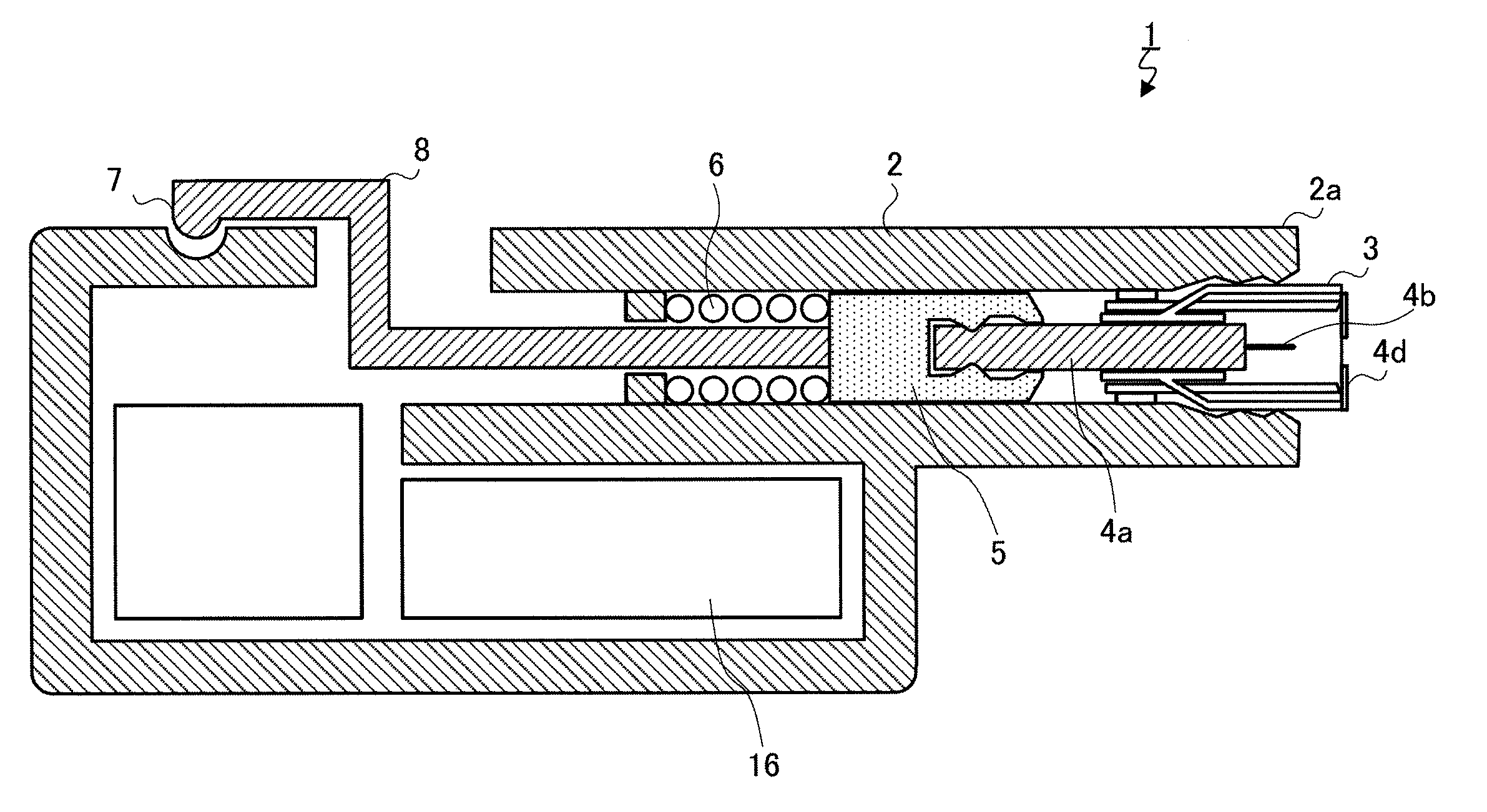
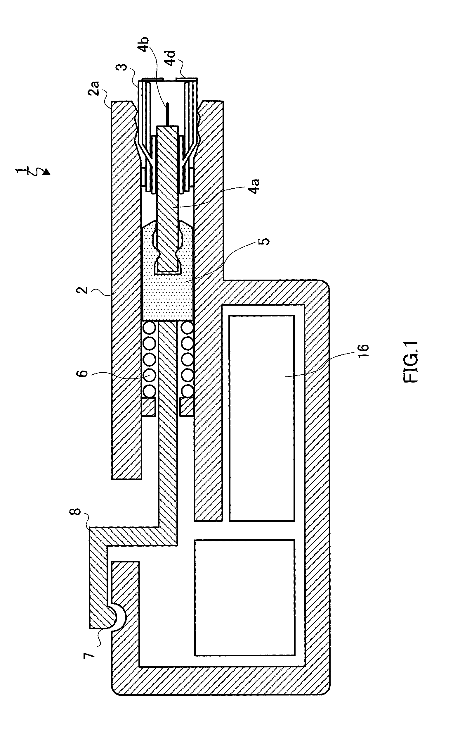
However, sensor block 3 used in blood test apparatus 1 has puncturing needle 4b and therefore may also become disadvantageous in terms of cost.
Blood test apparatus 11 has laser emitting apparatus 13, which makes the configuration complex, and is disadvantageous in terms of cost.

Method used


Image

  • Blood sensor and blood inspection device using it
  • Blood sensor and blood inspection device using it
  • Blood sensor and blood inspection device using it

Examples


Embodiment Construction

[0054]Hereinafter, an embodiment of the present invention will be explained based on the drawings.

[0055]1. Blood Sensor Unit and Blood Sensor Block

[0056]FIG. 6 is a conceptual diagram of blood sensor block 21 (hereinafter also referred to as “sensor block”) according to the present invention and a blood test apparatus to which sensor block 21 is attached. Sensor block 21 shown in FIG. 6 is composed of sensor unit 24 and needle unit 25 that is detachably attached to sensor unit 24. Sensor unit 24 is composed of sensor 22 and holder 23 to which sensor 22 is attached.

[0057]Sensor block 21 is detachably attached to blood test apparatus 27 (hereinafter also referred to as “needle puncturing type blood test apparatus”) that uses puncturing means 26 for driving puncturing needle 25b of needle unit 25. On the other hand, sensor unit 24 to which needle unit 25 is not attached is detachably attached to blood test apparatus 29 (hereinafter also referred to as “laser puncturing type blood test ...


PUM


Abstract

A blood sensor usable both for a blood inspection device that performs puncture with a puncturing needle and for a blood inspection device that performs puncture with laser. In concrete, this invention comprises a sensor unit having a holder and a blood sensor mounted to the holder and a needle unit having a slidable puncturing needle. The needle unit provides a blood sensor block detachably fitted to the inside of the holder of the sensor unit. The blood sensor block is applied to a needle-puncturing type blood inspection device. The sensor unit from which the needle unit is removed is applied to a laser-puncturing type blood inspection device.

Description

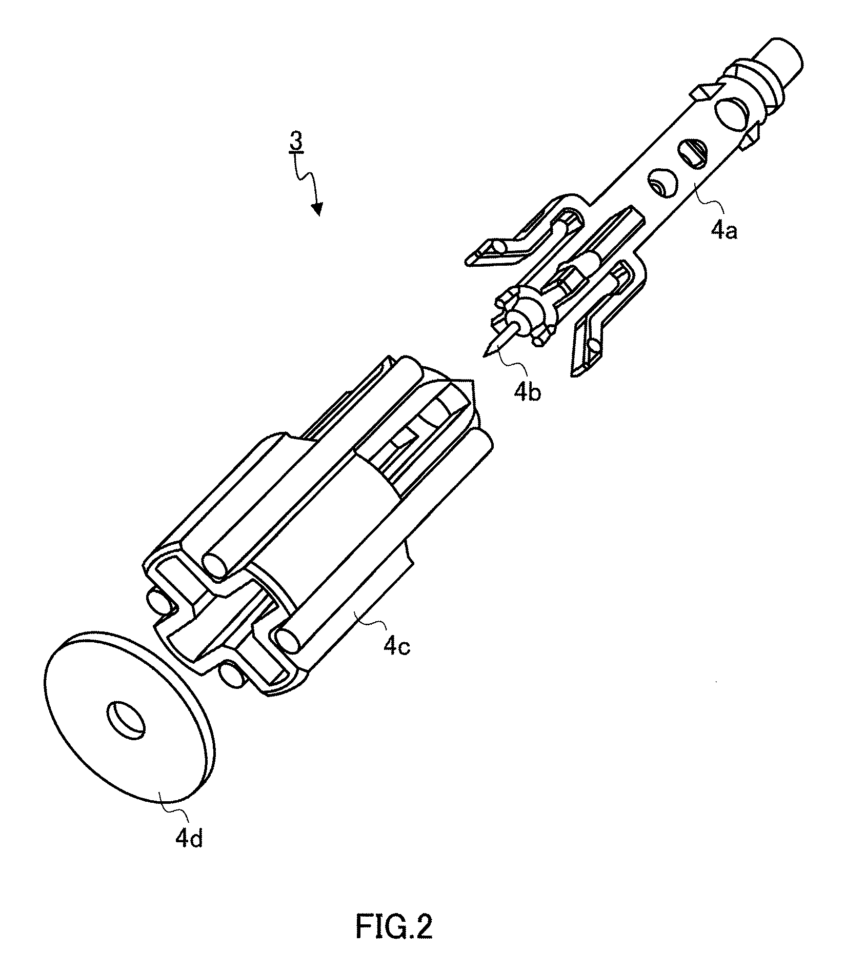
TECHNICAL FIELD [0001]The present invention relates to a blood sensor and a blood test apparatus to which the blood sensor is attached.BACKGROUND ART [0002]Diabetes patients need to measure their blood sugar level on a regular basis and inject insulin based on the measured blood sugar level to maintain a normal blood sugar level. To maintain this normal blood sugar level, diabetes patients need to measure the blood sugar level on a regular basis, and sample a small amount of blood from their fingertips with a blood test apparatus and measure the blood sugar level from the sampled blood.[0003]From the standpoint of a puncturing means, blood test apparatuses are broadly classified into apparatuses that perform puncturing by means of a puncturing needle and apparatuses that perform puncturing by means of laser light. FIG. 1 shows blood test apparatus 1 that performs puncturing by means of a puncturing needle. Blood test apparatus 1 is composed of: blood sensor block 3 (hereinafter also...

Claims


Application Information

Patent Timeline
IPC IPC(8): A61B5/151
CPCA61B5/1411A61B5/150022A61B5/150099A61B5/15019A61B5/150213A61B5/150358A61B5/150412A61B5/150519A61B5/15087A61B5/150954A61B5/15113A61B5/15117A61B5/15136A61B5/1519A61B5/15194A61B5/157A61B5/1405
Inventor AKIYAMA, TOSHIHIRO
Owner PANASONIC HEALTHCARE HLDG CO LTD
Learn More