Adjustable lifting tool

a technology of adjustable tools and lifting rods, which is applied in the direction of lifting devices, crowbars, etc., can solve the problems of difficult lifting of objects of significant size and weight, difficult to perform, and pose a risk of injury, so as to facilitate lifting and lowering, and achieve substantial size and weight

Inactive Publication Date: 2010-02-25
ELEVATORING MASTER
View PDF3 Cites 17 Cited by
  • Summary
  • Abstract
  • Description
  • Claims
  • Application Information

AI Technical Summary

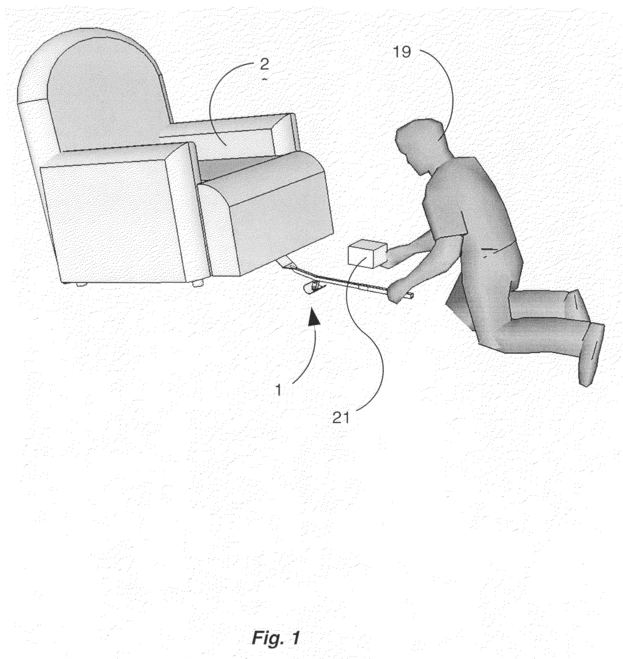
Benefits of technology

[0007]It has been recognized that it would be advantageous to develop a lifting tool which facilitates the lifting and lowering of an object of substantial size and weight. In addition, it has been recognized that it would be advantageous to develop a lifting tool which can be operated with one hand, allowing a user to simultaneously perform a second function in addition to the lifting. In addition, it has been recognized that it would be advantageous to develop a lifting tool which allows an object to be lifted while maintaining the integrity of the horizontal position of at least a part of the object. In addition, it has been recognized that it would be advantageous to develop a lifting tool which allows the lowering of a raised object into the same original horizontal position is desirable.

Problems solved by technology

The act of lifting an object of significant size and weight is difficult and may pose a risk of injury.
Further, the task of simultaneously lifting the object and retrieving an article, or placing an article under the object in a specific location, is especially inconvenient and difficult for a single person to perform.
Such a task requires the simultaneous effort of lifting, aligning, and affixing, which can often be inconvenient and difficult for one person to perform alone.
The performance of such tasks simultaneously is inconvenient and difficult.
Otherwise, if the entire sofa travels horizontally while it is being lifted, the location where the lifted portion will come to rest when it is lowered will be difficult to estimate.
For example, a dining room table which is allowed to scrape horizontally for any distance across a finished wood floor may cause marring or scratching to the floor.
Further, the dragging of an appliance, such as washing machine may cause damage to the floor and the appliance.

Method used


Image

  • Adjustable lifting tool
  • Adjustable lifting tool
  • Adjustable lifting tool

Examples


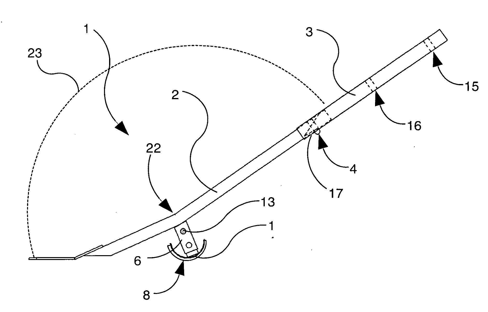
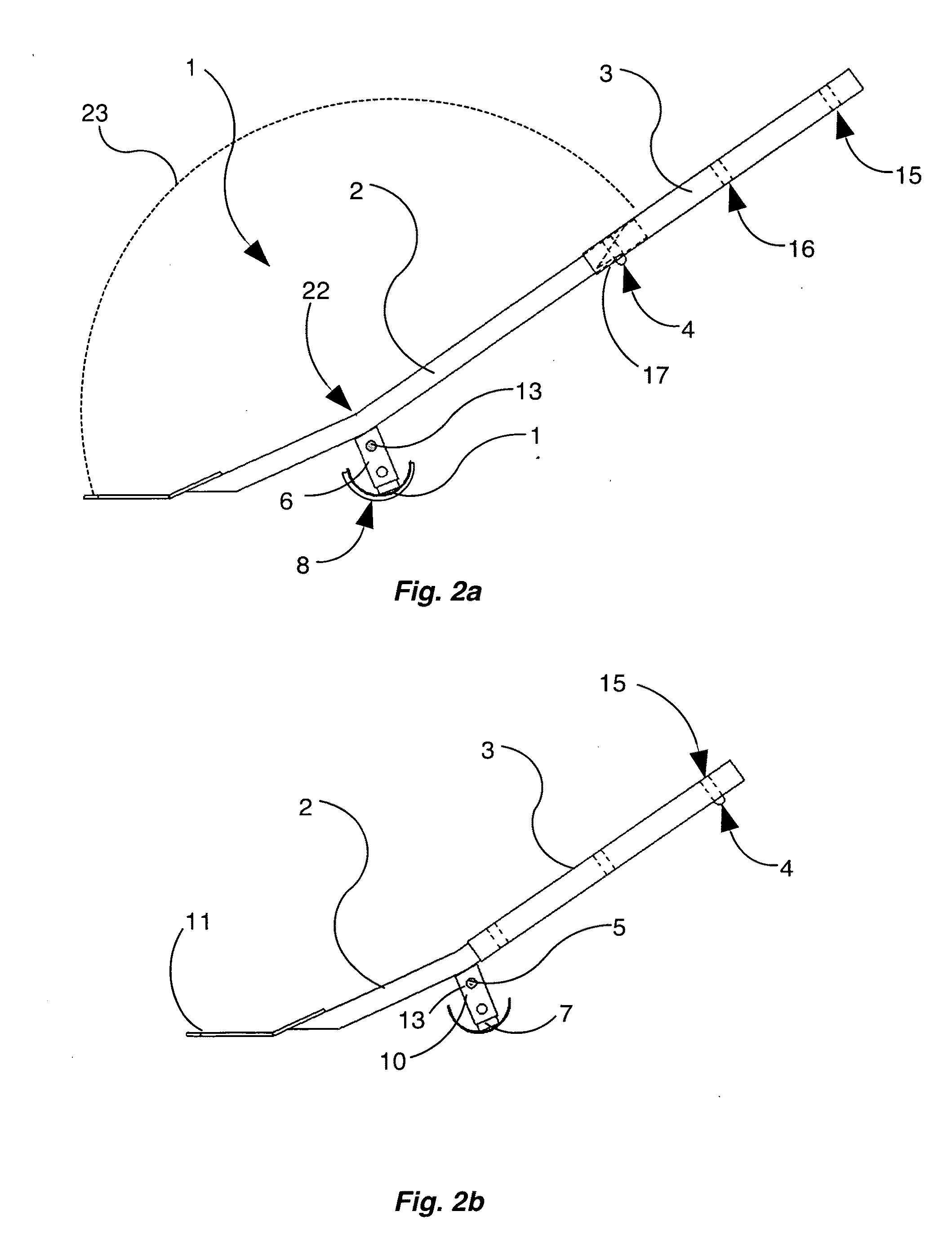
Embodiment Construction

[0026]Before the present lifting tool is disclosed and described, it is to be understood that this invention is not limited to the particular design and material disclosed herein, but is extended to equivalents thereof as would be recognized by those ordinarily skilled in the relevant arts. It should also be understood that terminology employed herein is used for the purpose of describing particular embodiment only, and is not intended to be limiting.

[0027]In describing and claiming the present invention, the following terminology will be used in accordance with the definitions set forth below.

[0028]As used herein, “vertex” refers to the point at which two lines intersect to form an angle.

[0029]As used herein, “obtuse” refers to an angle which is greater than 90.0 degrees, and less than 180.0 degrees.

[0030]As used herein, “acute” refers to an angle which is greater than 0.0 degrees, and less than 90.0 degrees.

[0031]As used herein, “ground” and “floor” may be used synonymously, and r...


PUM


Abstract

The present invention is a tool which provides a method for lifting. The tool has an adjustable handle member configured to be grasped by a user, joined to a lifting arm which is configured to engage an object to be lifted. The handle member and the lifting arm are rigidly connected at a vertex and form an obtuse angle there between. Further, the tool has an adjustable pedestal with a rocker base near the vertex, which allows forward and backward displacement of the tool during the raising and lowering an object.

Description

THE FIELD OF THE INVENTION[0001]The present invention relates generally to a lifting tool. More particularly, it concerns a tool for lifting an object which is configured to maintain the horizontal integrity of at least a portion of the lifted object.BACKGROUND OF THE INVENTION[0002]Often situations arise where an object, such as a piece of furniture, must be lifted in order to retrieve an article which is underneath the object, or to place an article, such as a support, underneath the object. The act of lifting an object of significant size and weight is difficult and may pose a risk of injury. Further, the task of simultaneously lifting the object and retrieving an article, or placing an article under the object in a specific location, is especially inconvenient and difficult for a single person to perform.[0003]Additional situations may arise where an object must be raised to a certain height and then fixed to a second object while suspended. For example, to install a tire on an ...

Claims


Application Information

Patent Timeline
Patent Type & Authority Applications(United States)
IPC IPC(8): B66F15/00B66F3/00
CPCB66F15/00
Inventor PATRICK, CHRISTOPHERCOLCOMBE, DANIEL J.
Owner ELEVATORING MASTER
Why Eureka
Try Eureka