Method for optimization in RFID location recognition system using blueprint

a location recognition system and blueprint technology, applied in the direction of wireless architecture, near-field systems using receivers, instruments, etc., can solve the problems of deteriorating efficiency, limited improvement of recognition, and much more expensive rfid readers than rf tags, so as to improve the effect of location recognition

Inactive Publication Date: 2010-02-25
PUSAN NAT UNIV IND UNIV COOPERATION FOUND
View PDF8 Cites 66 Cited by
  • Summary
  • Abstract
  • Description
  • Claims
  • Application Information

AI Technical Summary

Benefits of technology

[0012]Accordingly, the present invention has been made to solve the difficulty of optimizing the area for installing the RFID reader in the RFID-based building interior location recognition system occurring in the prior art, and an object of the present invention is to provide a method for optimization in an RFID location recognition system using a blueprint in which an optimum location for installing an RFID reader is determined using a blueprint so as to improve location recognition.
[0013]Another object of the present invention is to provide a method for installing a location recognition system which identifies a location of the RF tag so that the location recognition is improved in a building interior location recognition system using a fixed-type RFID reader and a mobile and passive RF tag.
[0014]Another object of the present invention is to provide a method for optimization in an RFID location recognition system which analyzes the dependence between the space for installing the RFID reader and the arrangement of the RFID reader using the blueprint and automatically determines an optimum location for installing the RFID reader based on the analyzed dependence result for improving the location recognition.
[0026]The step of analyzing the movement route includes the steps of: constructing the shortest route with respect to every pair of nodes available in the interior space graph model established through the step of specifying the building space for each story; giving the worth of the edge based on constructed shortest route information; normalizing the worth of the edge; and renewing the worth of the node.

Problems solved by technology

The RFID reader is much more expensive than the RF tag, so that a method for optimization of the area for installing the RFID reader has been required.
However, such a conventional art has a disadvantage in that it does not regard the space for installing the RFID reader, the location of the RFID reader, and dependence on the improvement of the location recognition, so that efficiency is deteriorated and the improvement of recognition is limited.

Method used


Image

  • Method for optimization in RFID location recognition system using blueprint
  • Method for optimization in RFID location recognition system using blueprint
  • Method for optimization in RFID location recognition system using blueprint

Examples


Embodiment Construction

[0049]Hereinafter, a method for optimization in an RFID location recognition system using a blueprint according to an exemplary embodiment of the present invention will be described in detail.

[0050]The characteristic and advantages of the method for optimization in the RFID location recognition system using the blueprint according to the present invention will be clearly understood with the detailed description of the exemplary embodiments.

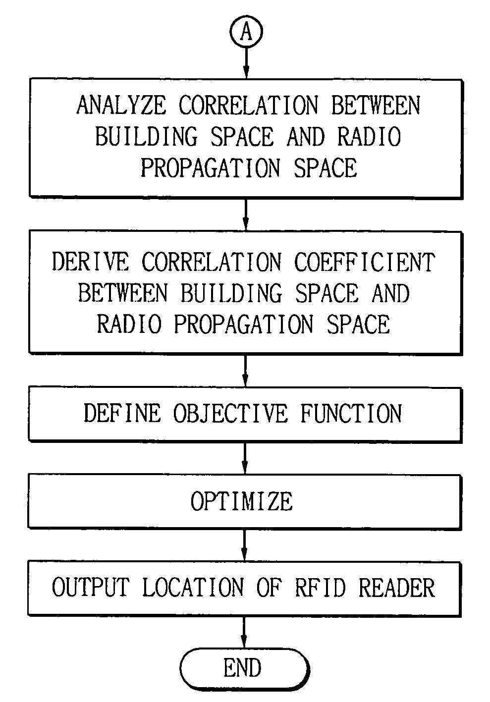
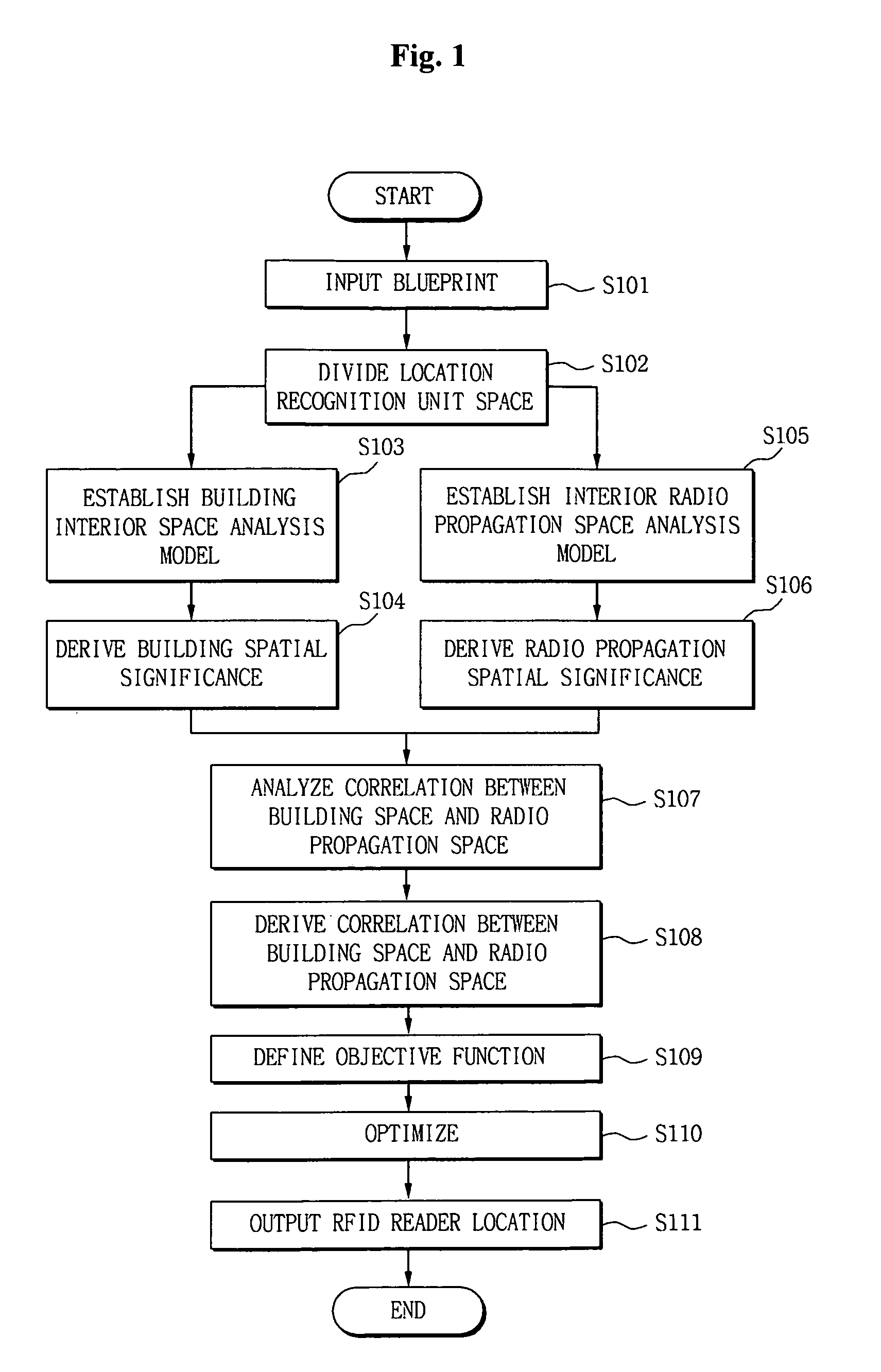
[0051]FIG. 1 is a flowchart illustrating a step of optimizing a RFID location recognition system using a blueprint according to the present invention.

[0052]The present invention extracts information from the blueprint and determines a location for installing an RFID reader in order to improve the RFID-based building interior location recognition system.

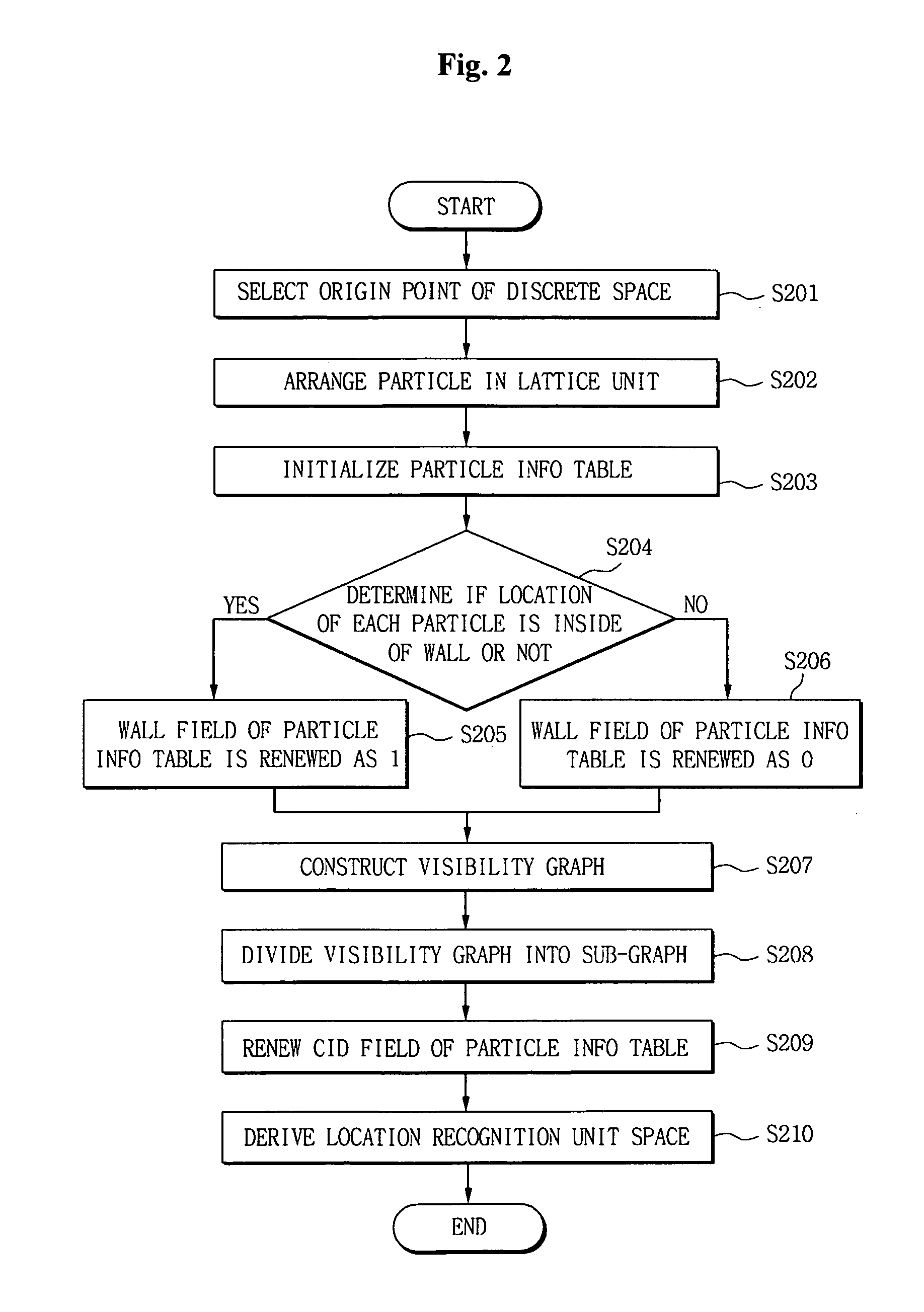
[0053]To this end, first, in the present invention, a location recognition unit space is divided from the blueprint.

[0054]The RFID-based location recognition system employs a scheme of recognizing a...


PUM


Abstract

A method for optimization in an RFID location recognition system is developed to use in a blueprint in which an optimum location for installing an RFID reader is determined for using a blueprint so as to improve location recognition. The method includes the steps of inputting a blueprint and dividing a location recognition unit space from the blueprint; establishing a building interior space analysis model and an interior radio propagation space analysis model and deriving a building spatial significance and a radio propagation spatial significance; analyzing correlation between a building space and a radio propagation space and deriving a correlation coefficient; and defining an objective function for determining a location of a RFID reader based on the building spatial significance, the radio propagation spatial significance, and the correlation coefficient between the building space and the radio propagation space and performing optimization.

Description

BACKGROUND OF THE INVENTION[0001]1. Field of the invention[0002]The present invention relates to an RFID-based building interior location recognition system, and more particularly to a method for optimization in an RFID location recognition system using a blueprint in which an optimum location for installing an RFID reader is determined using a blueprint so as to improve location recognition.[0003]2. Description of the Prior Art[0004]An RFID is a technology capable of recognizing a product using Radio Frequency (RF), and an RFID system includes an RF tag including an antenna and a chip, an RFID reader for recognizing the RF tag, and a server for processing tag information collected by the RFID reader.[0005]Especially, the RF tag can store information suitable for a use purpose of the RFID system, and is classified into an active tag having a built-in battery and a passive tag without a built-in battery.[0006]The RFID reader controls the transmission of the RF signal, retrieves and m...

Claims


Application Information

Patent Timeline
Patent Type & Authority Applications(United States)
IPC IPC(8): H04Q5/22
CPCG08C21/00H04Q2209/47H04Q9/00G06K17/00H04B5/00H04B5/02
Inventor TAK, SUNG WOOKIM, TAE HOONKIM, BYUNG HOONLI, KI JOUNESON, CHI WONLEE, DONG GEONKIM, YOUNG MANN
Owner PUSAN NAT UNIV IND UNIV COOPERATION FOUND
Why Eureka
Try Eureka