Apparatus and method for communicating between a central processing unit and a graphics processing unit

Active Publication Date: 2010-02-25
ARM LTD
View PDF8 Cites 44 Cited by
  • Summary
  • Abstract
  • Description
  • Claims
  • Application Information

AI Technical Summary

Benefits of technology

[0032]In one embodiment, the graphics processing unit supports multi-threaded execution, and comprises a scheduler for scheduling threads within the graphics processing unit. In one such embodiment, upon receipt by the graphics processing unit of any control signals provided from the central processing unit via the interface, the scheduler is arranged to schedule at least one thread for the processing operations associated with those control signals. In certain embodiments of the present invention, this can provide a mechanism for controlling the transition from execution of application code on the CPU to execution of that application code on the GPU, and back again, via a single execution thread.
[0033]In one embodiment, the scheduler is arranged to give higher priority to any thread associated with said control signals received via the interface than the priority given to other threads. Where the operations offloaded to the GPU through use of the additional mechanism are operations tightly coupled with the operations performed by the CPU, this provides a mechanism for ensuring that those offloaded operations are performed as quickly as possible within the GPU, thereby m

Problems solved by technology

In contrast, tightly coupled operations are those where the timing of the availability of the results is critical to the

Method used


Image

  • Apparatus and method for communicating between a central processing unit and a graphics processing unit
  • Apparatus and method for communicating between a central processing unit and a graphics processing unit
  • Apparatus and method for communicating between a central processing unit and a graphics processing unit

Examples


Embodiment Construction

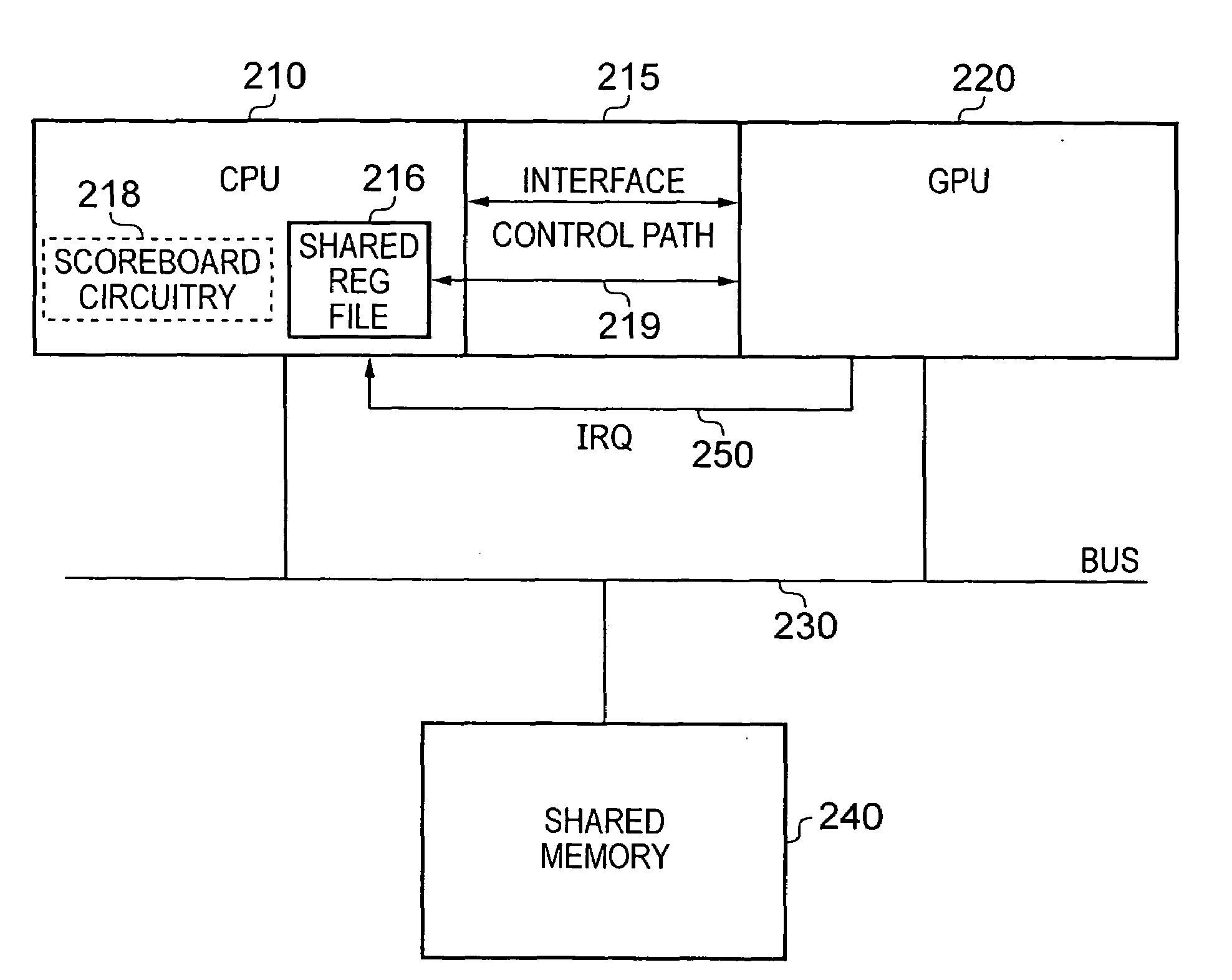
[0048]FIG. 3A is a block diagram schematically illustrating a data processing apparatus in accordance with one embodiment of the present invention. In one particular embodiment, the data processing apparatus takes the form of a System-on-Chip (SoC). In an analogous manner to the prior art of FIG. 1, a CPU 210 and a GPU 220 are coupled to a bus network 230, with shared memory 240 also being coupled to the bus network. The bus network 230 may incorporate one or more separate buses, and the shared memory 240 may or may not include one or more levels of cache.

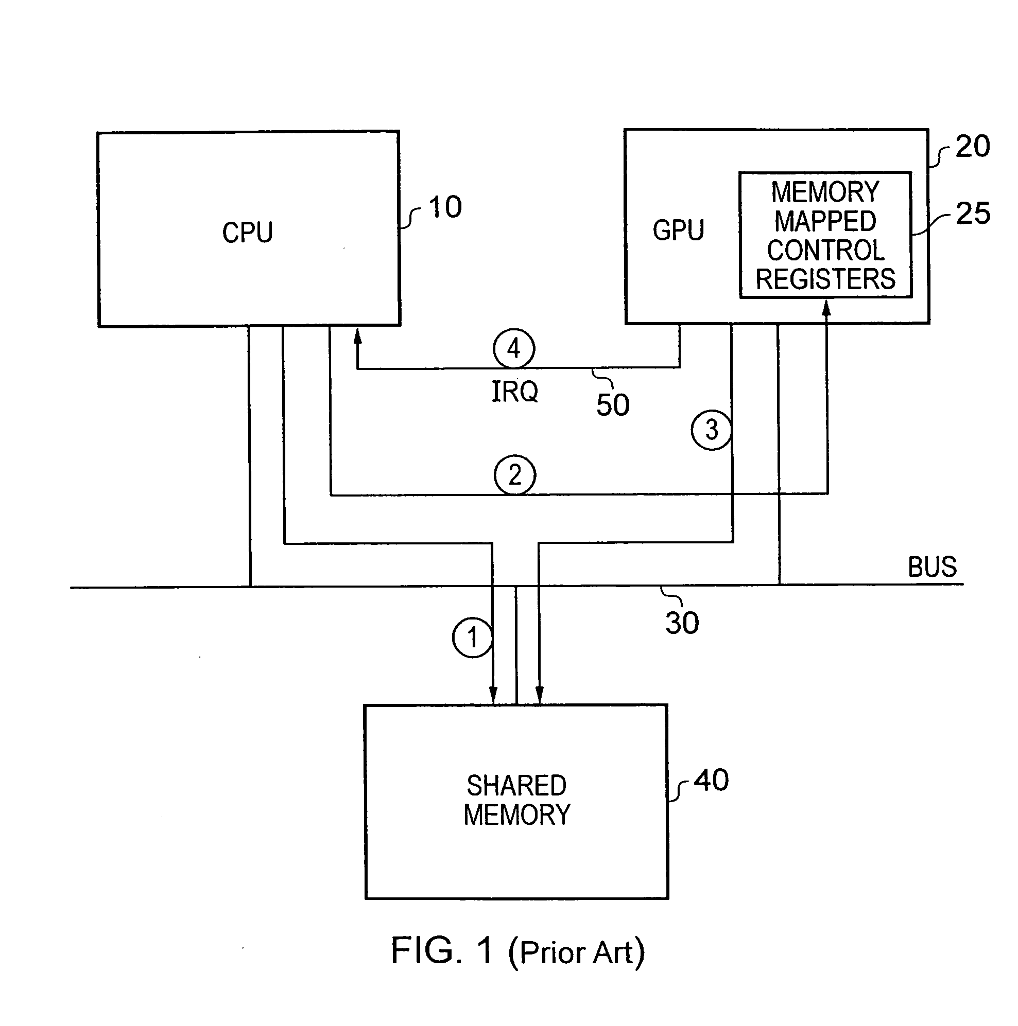
[0049]In accordance with a first mechanism for controlling the GPU, the CPU 210 may store one or more data structures in the shared memory 240, and via the bus 230 may additionally access one or more memory mapped control registers within the GPU so as to write various control values into the GPU in order to initiate performance of a sequence of graphics processing operations by the GPU. As with the early prior art example of FIG. ...


PUM


Abstract

The present invention provides an improved technique for communicating between a central processing unit and a graphics processing unit of a data processing apparatus. Shared memory is provided which is accessible by the central processing unit and the graphics processing unit, and via which data structures are shareable between the central processing unit and the graphics processing unit. A bus is also provided via which the central processing unit, graphics processing unit and shared memory communicate. In accordance with a first mechanism of controlling the graphics processing unit, the central processing unit routes control signals via the bus. However, in addition, an interface is provided between the central processing unit and the graphics processing unit, and in accordance with an additional mechanism for controlling the graphics processing unit, the central processing unit provides control signals over the interface. This enables the GPU to continue to be used to handle large batches of graphics processing operations loosely coupled with the operations performed by the CPU, whilst through use of the additional mechanism it is also possible to employ the GPU to perform processing operations on behalf of the CPU in situations where those operations are tightly coupled with the operations performed by the CPU.

Description

FIELD OF THE INVENTION[0001]The present invention relates to an apparatus and method for communicating between a central processing unit and a graphics processing unit, and in particular relates to techniques that enable the central processing unit to make more effective use of the resources of the graphics processing unit.BACKGROUND OF THE INVENTION[0002]Graphics processing units (GPUs) are typically designed to facilitate fast and efficient execution of common graphics processing operations, for example geometric processing functions such as dot, cross and matrix product calculations on vector inputs. Since GPUs are typically optimised for such operations, they can typically complete these tasks much faster than a central processing unit (CPU) even if such a CPU includes SIMD (single instruction multiple data) hardware.[0003]In a typical system-on-chip (SoC) environment, a CPU and a GPU may be coupled together via a bus infrastructure, with shared memory being utilised as a mechan...

Claims


Application Information

Patent Timeline
IPC IPC(8): G06F15/16G06F15/167
CPCG06F9/30076G06F9/30181G06F9/30189G06F9/3877G06T1/20G06F9/3851G06F15/167G06F15/173
Inventor FORD, SIMON ANDREWELLIS, SEAN TRISTRAMPLOWMAN, EDWARD CHARLES
Owner ARM LTD
Why Eureka
Try Eureka