Image pickup device

Active Publication Date: 2010-02-25
OLYMPUS CORP
View PDF4 Cites 19 Cited by
  • Summary
  • Abstract
  • Description
  • Claims
  • Application Information

AI Technical Summary

Benefits of technology

[0017]It is also preferable that the image pickup device of the present invention be further provided with a temporary storage member which temporarily stores the image data that is subject to processing by the pattern matching mem

Problems solved by technology

Among these, a panoramic imaging function is one of the functions with high appeal, however, as its operation is complex and difficult, and as it also involves many cases of failure in photography, it cannot be said to be a function that is mastered by the great majority of users.
However, as described below, the procedure of the panoramic imaging is very troublesome.
However, if the overlap portions from before and after the shifting of the imaging view field are shifted (if a vertical shift occurs when moving the imaging view field in the widthwise direction, and shooting), there is the problem that the imaging range in the direction that is not the direction of movement (the vertical direction in the case where the imaging view field is moved widthwise) is narrowed, because a rectangular region is extracted from the image that is finally obtained by stitching together all the images.
Otherwise, in the case where the subject images of the overlap portions from before and after the shifting of the imaging view field do not match, there is the problem that one cannot paste them together, or that one forcibly stitching them together with the result that an unnatural image is obtained.

Method used


Image

  • Image pickup device
  • Image pickup device
  • Image pickup device

Examples


Embodiment Construction

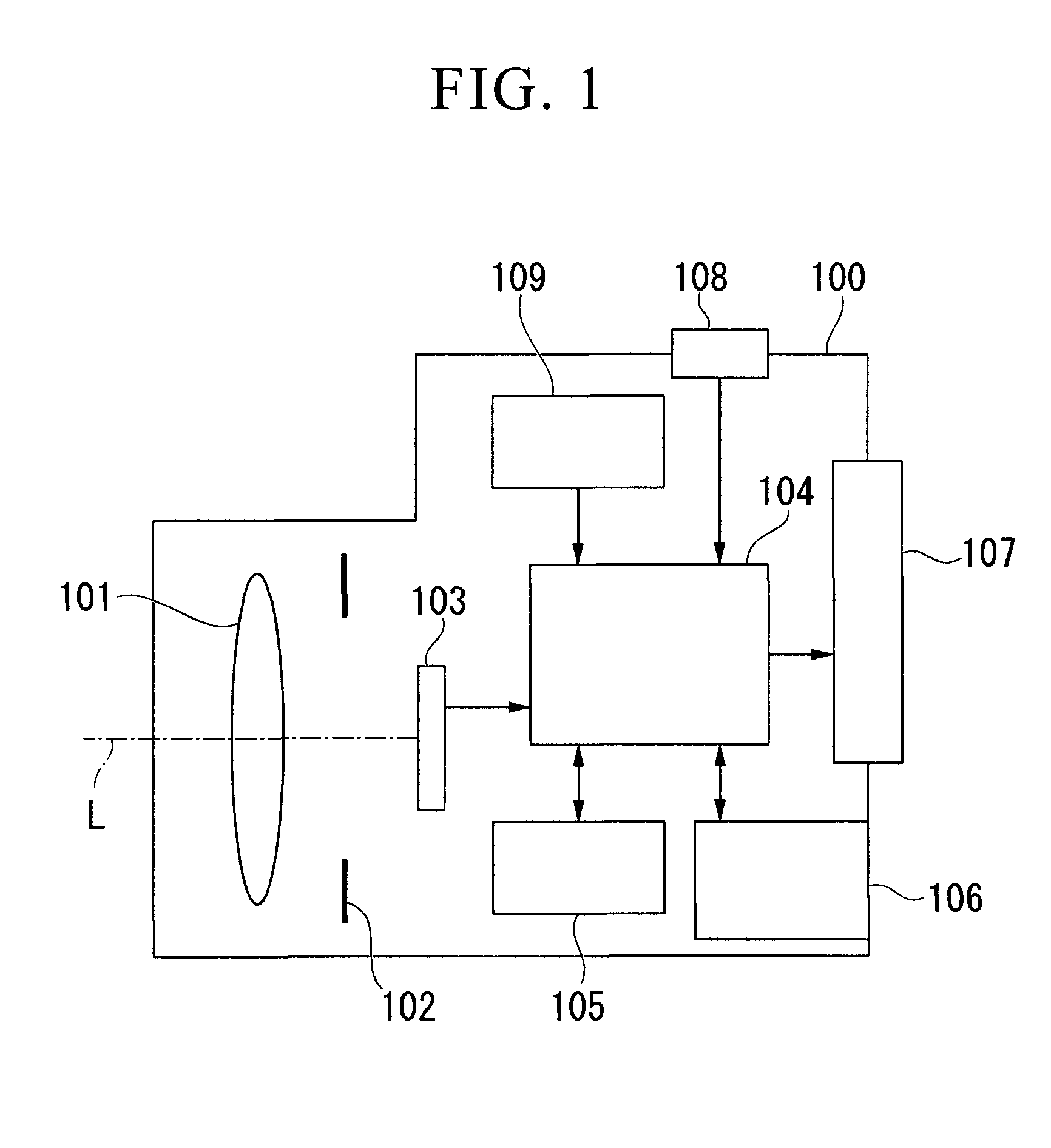
[0027]Embodiments of the present invention are described below with reference to drawings. FIG. 1 shows the configuration of a camera (image pickup device) of one embodiment of the present invention. The camera shown in FIG. 1 is provided with an imaging optical system 101 within a camera body 100, aperture mechanism 102, CCD (Charged Coupled Device) 103, system controller 104, memory 105, memory card 106, TFT (Thin Film Transistor) 107, switch 108, and angular velocity sensor 109.

[0028]The imaging optical system 101 forms the subject image in the CCD 103 (corresponds to the imaging member). The aperture mechanism 102 regulates the amount of luminous flux from a subject by changing the diameter of an opening that is disposed perpendicular to an optical axis L. A subject image formed by the imaging optical system 101 is converted into electrical signals by the CCD 103, and is read out as video signals based on synchronous signals from the system controller 104 (corresponds to the ima...


PUM


Abstract

In this image pickup device, a system controller uses pattern matching to detect regions where patterns match between images based on multiple sets of image data. Subsequently, the system controller conducts alignment based on the regions that are matched by pattern matching with respect to the multiple sets of image data that are generated by multiple imagings in a exposure time shorter than a normal exposure time while the imaging view field changes. Furthermore, the system controller adds the respective sets of image data after alignment, and generates image data corresponding to a view field that is wider than the imaging view field of a CCD. According to this image pickup device, motion blur can be reduced.

Description

BACKGROUND OF THE INVENTION[0001]1. Field of the Invention[0002]The present invention relates to an image pickup device which generate a composite image by multiple shots, and which generates a panoramic image with a widened imaging view field.[0003]Priority is claimed on Japanese Patent Application No. 2008-210565, filed Aug. 19, 2008, the content of which is incorporated herein by reference.[0004]2. Background Art[0005]In recent years, in conjunction with a trend toward increasing functional sophistication, a variety of functions have been loaded into digital cameras to appeal to users. Among these, a panoramic imaging function is one of the functions with high appeal, however, as its operation is complex and difficult, and as it also involves many cases of failure in photography, it cannot be said to be a function that is mastered by the great majority of users. By utilizing the panoramic imaging function, the user takes multiple shots while shifting the imaging view field, and a...

Claims


Application Information

Patent Timeline
IPC IPC(8): H04N5/228G06K9/62
CPCH04N5/23238H04N5/232H04N23/698
Inventor TSUCHIYA, HITOSHI
Owner OLYMPUS CORP
Why Eureka
Try Eureka