Optical Beam Splitter

a splitter and optical beam technology, applied in the field of optics, can solve the problems of reducing the intensity of the two light beams exiting the optical splitter, propagating loss of the input light beam, etc., and achieve the effect of reducing or eliminating at least some of the disadvantages and problems

Inactive Publication Date: 2010-02-25
FUJITSU LTD
View PDF9 Cites 6 Cited by
  • Summary
  • Abstract
  • Description
  • Claims
  • Application Information

AI Technical Summary

Benefits of technology

[0005]The present disclosure provides an optical beam splitter that substantially eliminates or reduces at least some of the disadvantages and problems associated with previous methods and systems.

Problems solved by technology

This results in a propagation loss in the input light beam and thus a decrease in the intensity of the two light beams exiting the optical splitter.

Method used


Image

  • Optical Beam Splitter
  • Optical Beam Splitter
  • Optical Beam Splitter

Examples


Embodiment Construction

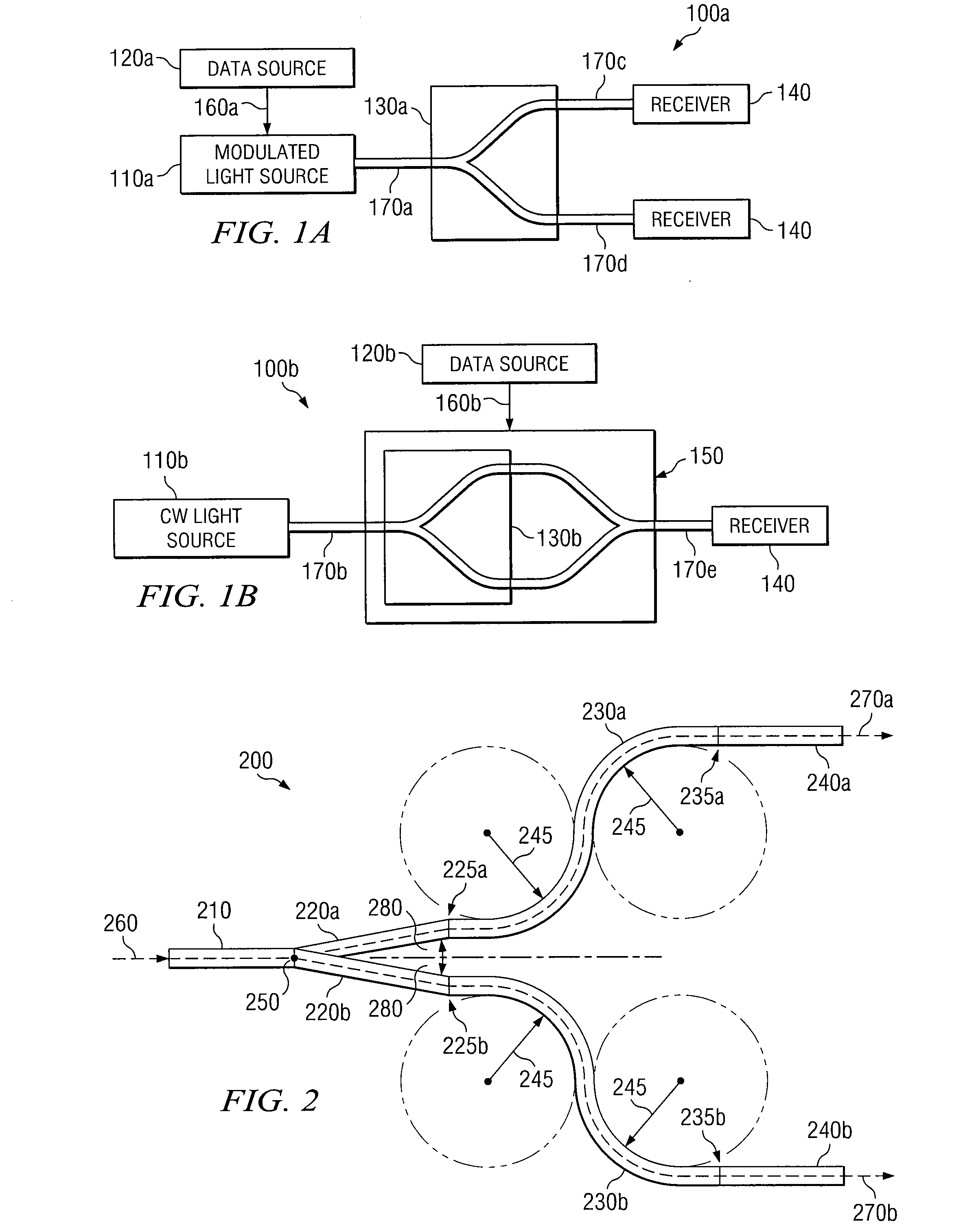
[0015]FIGS. 1A and 1B depict example optical systems 100a and 100b where a particular embodiment may be utilized. Optical systems 100 include a modulated light source 110a, a continuous wave light source 110b, data sources 120a and 120b, optical splitters 130a and 130b, one or more receiving devices 140, and a modulator 150. Light sources 110 typically consist of lasers or any other device that produces a light beam. Data source 120a is coupled to modulated light source 110a via electrical data link 160a, and data source 120b is coupled to modulator 150 via electrical data link 160b. Data sources 160 provide data to be modulated onto a light beam. Modulator 150 includes an optical splitter 130b and modulates data from data source 120b onto a continuous wave light beam received from continuous wave light source 110b. Light sources 110 are coupled to optical splitters 130 via optical links 170. Receiving devices 140 are also coupled to optical splitter 130a and modulator 150 via optic...


PUM


Abstract

An optical beam splitter includes an input waveguide, two or more branching arms, two or more fan-out arms, and two or more output waveguides. The input waveguide receives an input light beam. The two or more branching arms are coupled to the input waveguide at a separation point and split the input light beam at the separation point into two or more light beams. Each fan-out arm is coupled to one of the branching arms and fans-out one of the two or more light beams to a predetermined output pitch. Each output waveguide is coupled to one of the fan-out arms and transmits one of the two or more light beams out of the optical beam splitter.

Description

TECHNICAL FIELD[0001]This disclosure relates in general to optics and more particularly to an optical beam splitter.BACKGROUND[0002]The splitting of an optical beam into two or more optical beams is an important function in optical communication systems. Optical beam splitters enable a single optical beam from a source such as a laser to be supplied to more than one device. As a result, optical beam splitters are utilized in many devices including splitter arrays, optical interconnects, modulators, and the like.[0003]Typical 1×2 optical splitters consist of an input waveguide, two fan-out arms coupled to the input waveguide at a separation point, and two output waveguides. An input light beam enters the optical splitter and travels through the input waveguide to the separation point. At the separation point, the light beam is split into two light beams by being forced to enter the two fan-out arms. The two light beams then travel through the fan-out arms and out of the optical split...

Claims


Application Information

Patent Timeline
Patent Type & Authority Applications(United States)
IPC IPC(8): G02B6/26
CPCG02B6/125
Inventor LEE, MICHAEL G.GLEBOV, ALEXEI L.ZHOU, DASHUN STEVE
Owner FUJITSU LTD
Why Eureka
Try Eureka