
Surface treated aluminum nitride baffle

a technology of aluminum nitride and surface treatment, which is applied in the field of aluminum nitride baffle, can solve the problems of reducing the thermal conductivity of the baffle, undesirably interfering with the adhesion of silicon oxide, and baffle being susceptible to damag

Active Publication Date: 2010-02-25
APPLIED MATERIALS INC
View PDF12 Cites 38 Cited by
  • Summary
  • Abstract
  • Description
  • Claims
  • Application Information

AI Technical Summary

Benefits of technology

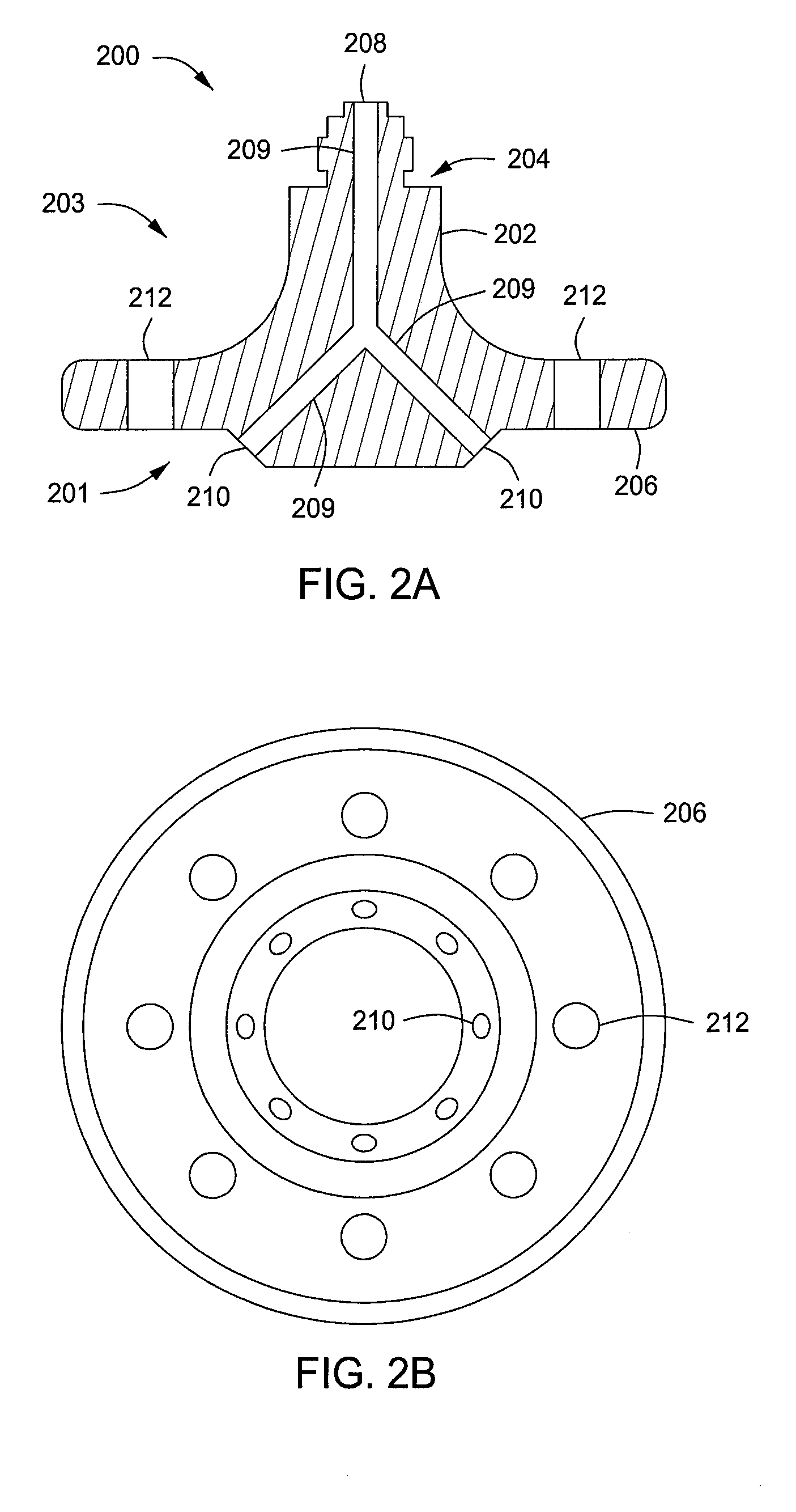
[0032]Thus, the inventors believe that eliminating or reducing the excess metal oxide on the surface of the baffle may provide advantages over conventional aluminum nitride baffles. Accordingly, in some embodiments, the baffle 200 may have a ratio of aluminum nitride to metal oxide on the surface of the body 202 that is greater than or equal to the ratio within the body 202. In some embodiments, the baffle 200 may have substantially no excess metal oxide on the surface of the body 202.

Problems solved by technology

Unfortunately, although aluminum nitride baffles have some favorable properties, other problems remain.
However, these binding agents, present on the surface of the baffle after sintering, undesirably interfere with the adhesion of a silicon oxide (SiO2) layer during seasoning of the baffle prior to substrate processing.
However, the poorly adhered silicon oxide seasoning layer can flake off the surface of the baffle, thus contaminating a substrate being processed, and may also leave the baffle susceptible to damage from reactive gases supplied during substrate processing or chamber cleaning.
Although this problem may be eliminated by not using metal oxide binding agents, such an approach would undesirably reduce the thermal conductivity of the baffle.

Method used


Image

  • Surface treated aluminum nitride baffle
  • Surface treated aluminum nitride baffle
  • Surface treated aluminum nitride baffle

Examples


Embodiment Construction

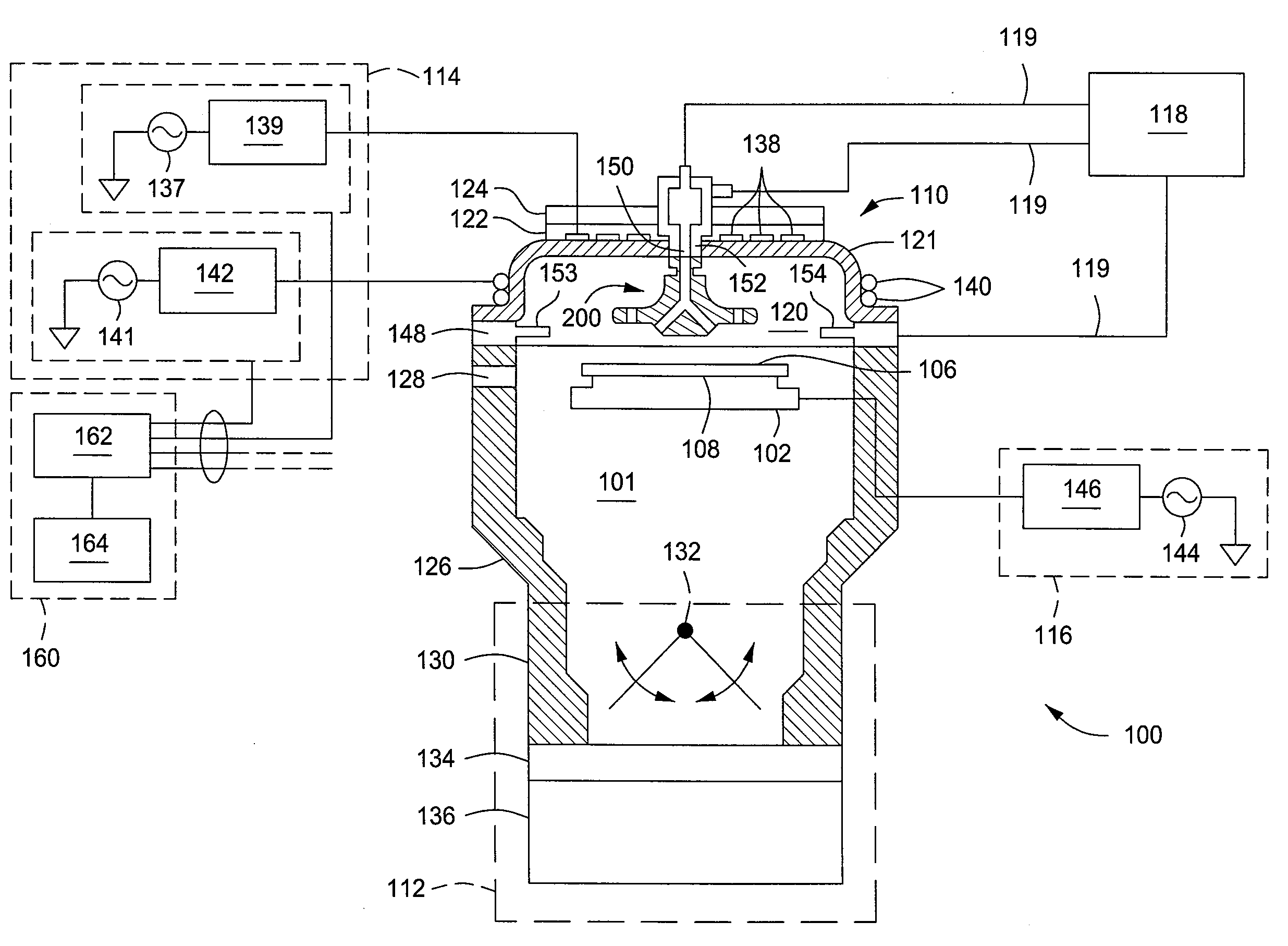
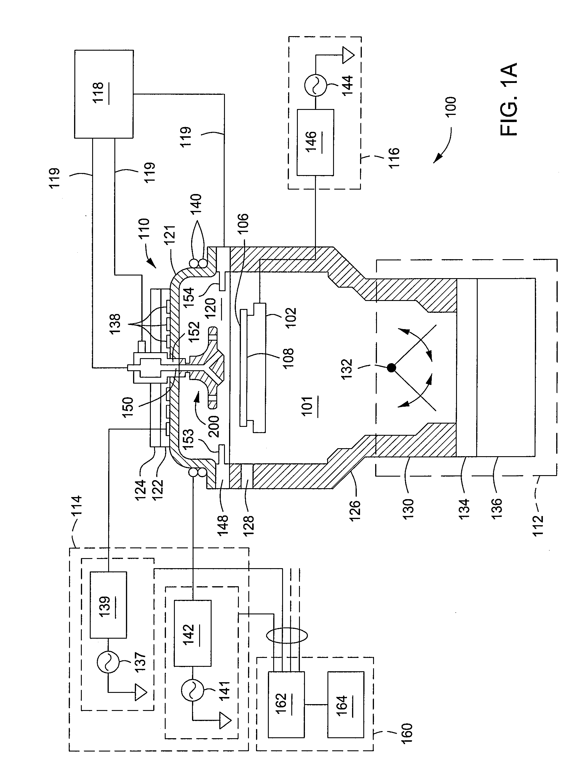
[0019]Methods and apparatus for processing semiconductor substrates using an improved aluminum nitride baffle are provided herein. In some embodiments, a baffle for use in a semiconductor process chamber includes a body comprising aluminum nitride and a metal oxide binding agent. A ratio of aluminum nitride to metal oxide on a surface of the body is greater than the ratio within the body. The reduced quantity of metal oxide on the surface of the body facilitates improved adhesion of a silicon oxide seasoning layer to the surface of the baffle, which may further prevent contamination of a substrate during processing by particles that may otherwise flake off of the aluminum nitride baffle, and may further protect the baffle from damage by reactive process gases. In some embodiments, a method of manufacturing the aluminum nitride baffle is provided. The manufacturing method may advantageously facilitate fabricating an aluminum nitride baffle having a ratio of aluminum nitride to metal ...


PUM

PropertyMeasurementUnit
Flow rateaaaaaaaaaa
Volumeaaaaaaaaaa
Ratioaaaaaaaaaa

Abstract

Methods and apparatus relating to aluminum nitride baffles are provided herein. In some embodiments, a baffle for use in semiconductor process chambers may include a body comprising aluminum nitride and a metal oxide binding agent, wherein a ratio of aluminum nitride to metal oxide on a surface of the body is greater than or equal to the ratio within the body. In some embodiments, the body may have a center stem and an outer annulus coupled to and extending radially outwards from a lower portion of the center stem. In some embodiments, a method of fabricating a baffle may include sintering aluminum, nitrogen, and a metal oxide binding agent to form a body of the baffle, the body having excess metal oxide binding agent disposed on a surface thereof; and removing a bulk of the excess metal oxide binding agent from a surface of the body.

Description

BACKGROUND OF THE INVENTION[0001]1. Field of the Invention[0002]Embodiments of the present invention generally relate to semiconductor processing equipment and more particularly to an aluminum nitride baffle for processing semiconductor substrates.[0003]2. Description of the Related Art[0004]In some high density plasma chemical vapor deposition (HDP-CVD) processing chambers, a baffle may be used for gas injection and distribution during substrate processing. Baffles for HDP-CVD chambers have typically been constructed from aluminum oxide (Al2O3). However, with the use of the high RF power HDP-CVD processes to access smaller device nodes, elevated temperatures result in the reaction of the aluminum oxide with process gases, for example, nitrogen trifluoride (NF3), which can be used as a cleaning gas for HDP-CVD chambers. Thus, owing to improved thermal conductivity, among other factors, aluminum oxide baffles have been replaced with aluminum nitride (AlN) baffles.[0005]Unfortunately,...

Claims


Application Information

Patent Timeline
IPC IPC(8): C23C16/00B29C67/04H01L21/30
CPCC23C16/45591C23C16/4404H01J37/32449C23C16/45561C23C16/45565C23C16/45563C04B35/581C04B40/0092H01L21/02271H01L21/0262H01L21/28556
Inventor RASHEED, MUHAMMAD M.LUBOMIRSKY, DMITRY
Owner APPLIED MATERIALS INC
Learn More