Display apparatus and method for a control unit for an environmental control system

a control unit and display apparatus technology, applied in lighting and heating apparatus, heating types, instruments, etc., can solve the problems of cumbersome use of some features, insufficient detail of control units for use with hvac systems, complex hvac systems, etc., and achieve the effect of convenient programing

Inactive Publication Date: 2010-02-25
LENNOX IND +1
View PDF76 Cites 90 Cited by
  • Summary
  • Abstract
  • Description
  • Claims
  • Application Information

AI Technical Summary

Benefits of technology

[0009]It is, therefore, a feature of the present invention to provide an improved control unit for use with HVAC systems that is intuitively easier to program.
[00

Problems solved by technology

HVAC systems have become more complex in recent years.
Control units for use with HVAC systems have not been sufficiently detailed and varied in the information provided for a user to permit efficient use of features of the HVAC system.
Complexity in programming and displaying information has caused some confusion to the extent that some users do not employ all of the featur

Method used


Image

  • Display apparatus and method for a control unit for an environmental control system
  • Display apparatus and method for a control unit for an environmental control system
  • Display apparatus and method for a control unit for an environmental control system

Examples


Embodiment Construction

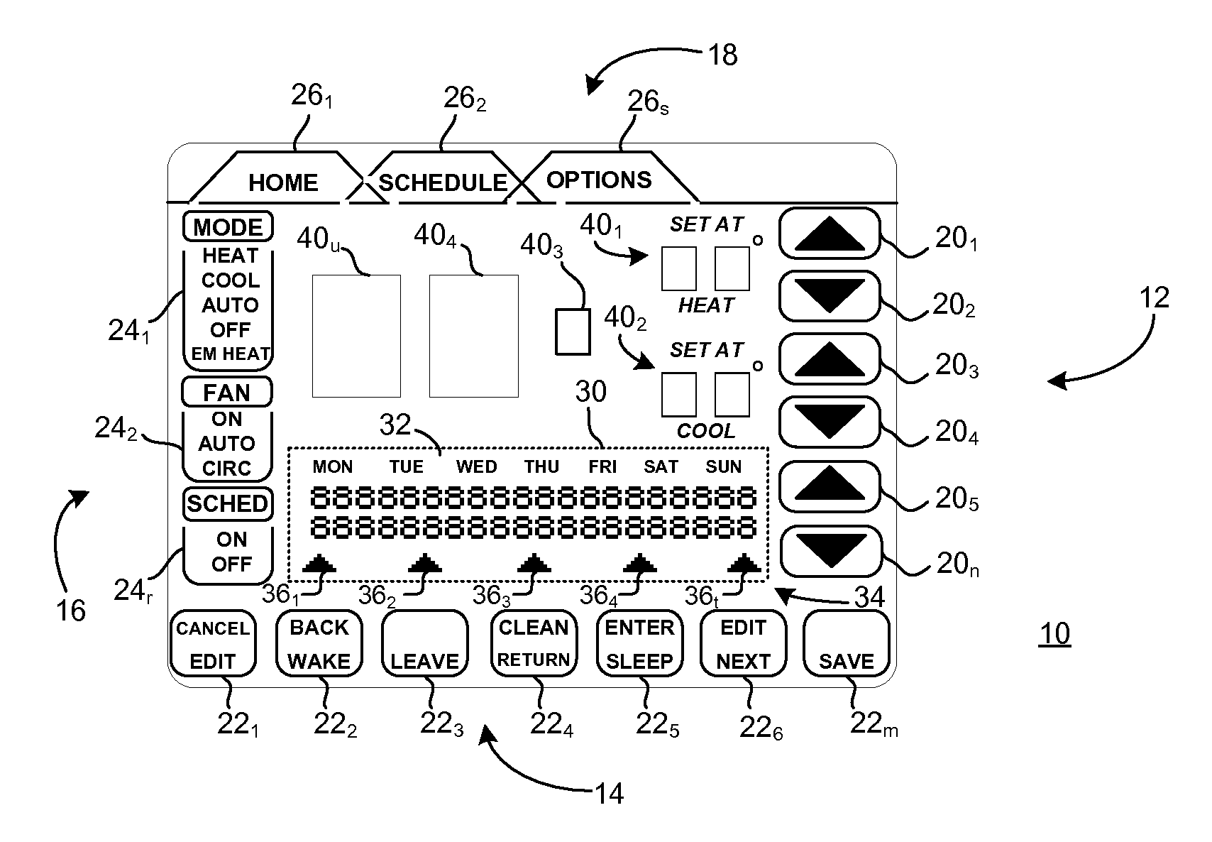
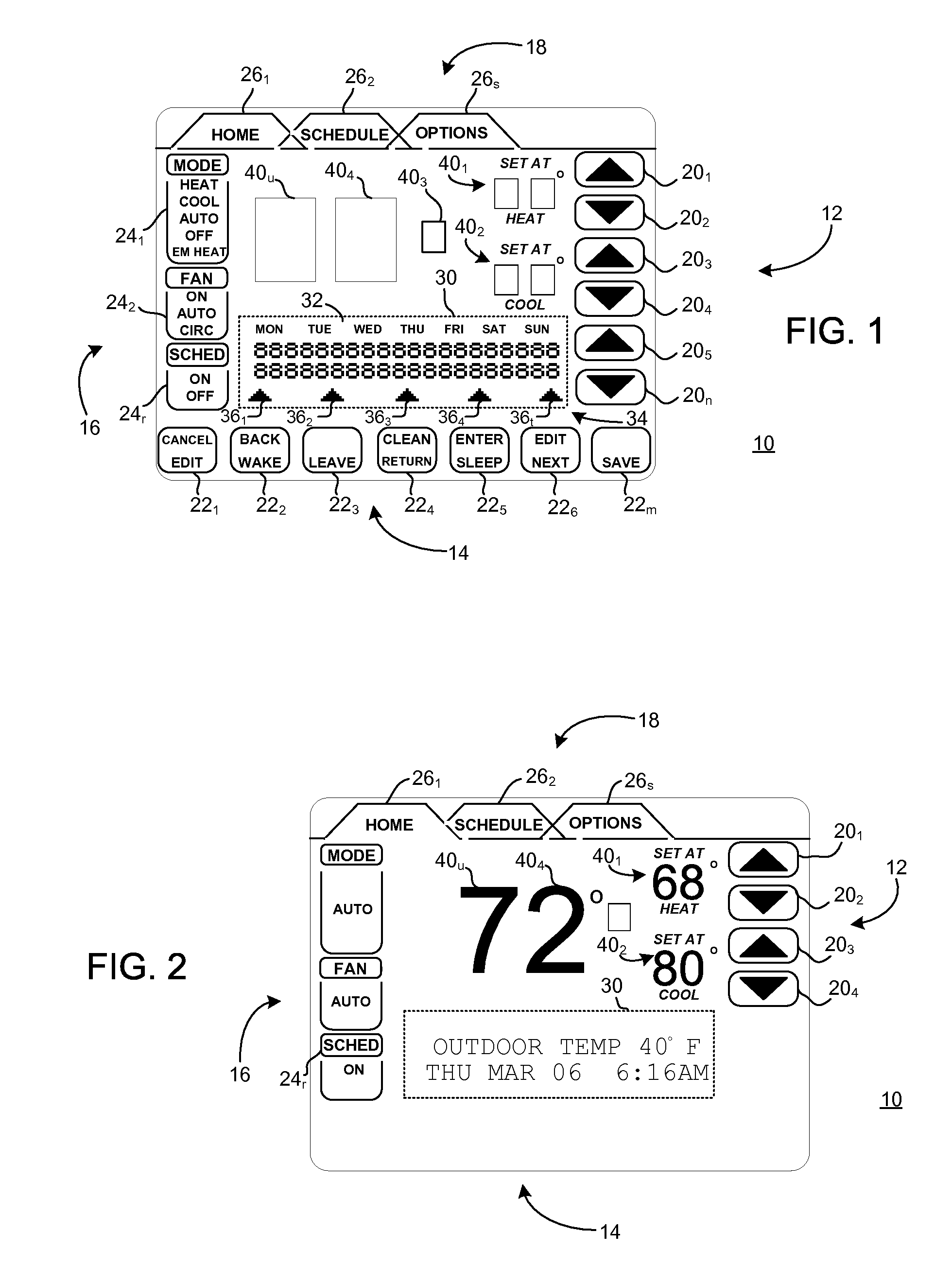
[0063]FIG. 1 is a plan view of a thermostat display configured according to the teachings of the present invention. In FIG. 1, a thermostat display 10 may be appropriate for use with a control unit in an environmental control system such as, by way of example and not by way of limitation, a Heating Ventilating Air Conditioning (HVAC) system. Display 10 may include a plurality of touch responsive loci configured to respond to pressure applied to respective touch responsive loci for effecting respective responses.

[0064]In the exemplary display 10 illustrated FIG. 1, touch responsive loci 12 may be generally indicated by delineated directional areas 201, 202, 203, 204, 205, 20n annotated with directional symbols indicating alteration or adjustment of a parameter up or down. Actuation may be carried out in any known manner, preferably by pressing or depressing an individual locus 20n in the manner of a touch screen input device known by those skilled in the art of design of control devi...


PUM


Abstract

A display apparatus for a control unit in an environmental control system; the display apparatus including: a display area presenting a plurality of first loci, a plurality of second loci and at least one third locus; each respective first locus of the plurality of first loci being responsive to pressure for effecting a respective response; each respective second locus of the plurality of second loci presenting information using a fixed segment data format; at least one third locus of the at least one third locus presenting information using a dot matrix data format.

Description

CROSS REFERENCE TO RELATED APPLICATION[0001]The present application is related to U.S. patent application Ser. No. ______ entitled “DISPLAY APPARATUS AND METHOD FOR ENTERING A REMINDER IN A CONTROL UNIT FOR AN ENVIRONMENTAL CONTROL SYSTEM,” filed ______, which is assigned to the current assignee hereof.FIELD OF THE INVENTION[0002]The present invention is directed to Heating Ventilating Air Conditioning (HVAC) system controller devices, and especially to a thermostat or other control unit for use with a HVAC system. The present invention is particularly useful with a residential HVAC system.BACKGROUND OF THE INVENTION[0003]HVAC systems have become more complex in recent years. Control units for use with HVAC systems have not been sufficiently detailed and varied in the information provided for a user to permit efficient use of features of the HVAC system. Complexity in programming and displaying information has caused some confusion to the extent that some users do not employ all of ...

Claims


Application Information

Patent Timeline
IPC IPC(8): G06F3/041
CPCB60H1/00985F24F2011/0091B60H1/00657G05D23/1902F24F11/00G05D23/1951B60H1/0065F24F11/001F24F11/0086G06F3/04847G06F3/0484F24F2011/0057F24F11/0012G05D23/00B60H1/00642F24F11/0009F24F2221/32F24F2011/0068G06F3/048F24F11/30F24F2110/00F24F2110/10F24F2120/20F24F11/56F24F11/52F24F11/523F24F11/63F24F11/65
Inventor THORSON, TIMOTHY H.WALLAERT, TIMOTHY E.
Owner LENNOX IND
Why Eureka
Try Eureka