Inkjet dyeing method and apparatus

a dyeing method and dyeing technology, applied in the field ofinkjet dyeing methods and apparatuses, can solve the problems of increasing environmental burden, inconvenient high-speed printing, and disadvantages of recording methods described in patent documents 2 and 2, so as to reduce environmental burden, reduce equipment costs, and easy subject to continuous printing

Active Publication Date: 2010-03-04
JOYSON SAFETY SYST JAPAN GK
View PDF5 Cites 8 Cited by
  • Summary
  • Abstract
  • Description
  • Claims
  • Application Information

AI Technical Summary

Benefits of technology

[0014]It is preferable that the feeding section and the transporting section be structured so as to give the textile a certain amount of elongation. Also, the control unit may be structured so that ejecting timing of the ink is adjusted to suit the elongation of the textile on the front surface printing line and the rear surface printing line. The inkjet dyeing method and apparatus according to the present invention described above allow a textile with its front surface subjected to printing to be inverted so as to enable its rear surface to be ready for printing, thereby allowing both surfaces of the textile to be easily subjected to continuous printing. Use of inkjet systems as a method for dyeing a belt-like textile such as the seat belt webbing enables a textile to be dyed without using a dyeing solution that requires waste solution treatment processes, thereby reducing burdens on the environment. Also, it eliminates necessity for installations such as a gas tank or a steam boiler or the like, thereby downsizing equipments, and reducing cost and burdens on the environment. Furthermore, it enables dyeing without immersing the textile in the dye solution, thereby allowing various colors and patterns to be printed. Therefore, it gives an additional value of design to the seat belt webbing that would otherwise appear to be monotonous. In addition, product information contained in a tag, which conventionally has been attached to the seat belt webbing after the dyeing process, can be printed on the surface of the seat belt webbing, resulting in a reduction in manufacturing man-hours.
[0015]The textile is transported in such a manner that both-side printing can be provided simultaneously, thereby effectively reducing the size of the apparatus. Also, for textile inversion, the textile is smoothly inverted by inverting the textile by 90 degrees at a time, thereby preventing the front and rear surfaces of the textile from coming into contact with each other during the inversion which causes ink wear or color migration. Furthermore, the pre-inverted textile and the post-inverted textile run in parallel, thereby allowing the textile to be transported in such a manner that the front surface printing line and the rear surface printing line are in parallel with each other and are directed toward the same direction and also allowing both sides of the textile to be simultaneously printed at one path, resulting in improved printing efficiency.
[0016]Also, an appropriate drying step inserted after the front surface printing and rear surface printing allows excessive ink to be dried, thereby suppressing color migration to the transporting roller. Furthermore, the second drying step (second drying section) for securely drying both sides of the textile allows ink to produce color and also allows ink to be fixed to the textile.
[0017]Also, a certain amount of elongation provided to the textile allows printing accuracy to be improved, thereby creating beautiful patterns on the textile under normal conditions (service conditions). Furthermore, even if yellow, magenta, cyan, and black colors are over-painted, ink misalignment can be prevented, thereby allowing beautiful designs or patterns to be printed.
[0018]Also, disposing the drying section and the inverting section below the printing sections (front surface printing section and rear surface printing section) can reduce dead spaces inside the inkjet dyeing apparatus, thereby downsizing the apparatus.

Problems solved by technology

The dyeing method disclosed in Patent Document 1, however, causes problems that only one-color dyeing with no patterns can be achieved since the webbing is immersed in the dye solution, that a large space is required for a water bath for a dye solution and a hot-water washing solution, and that it is necessary to treat a waste dyeing solution and to install a gas tank and a steam boiler and the like, thereby increasing a burden on the environment.
The recording method described in Patent Document 2 also has a disadvantage, and is mainly used in single-side printing since it is intended mainly for a cloth and textile used for clothing and wallpaper.
Furthermore, the recording method described in Patent Document 2 is not suitable for a high-speed printing because an ink head is moving on a printed surface while ejecting an ink due to its extended range of printing.

Method used


Image

  • Inkjet dyeing method and apparatus
  • Inkjet dyeing method and apparatus
  • Inkjet dyeing method and apparatus

Examples


first embodiment

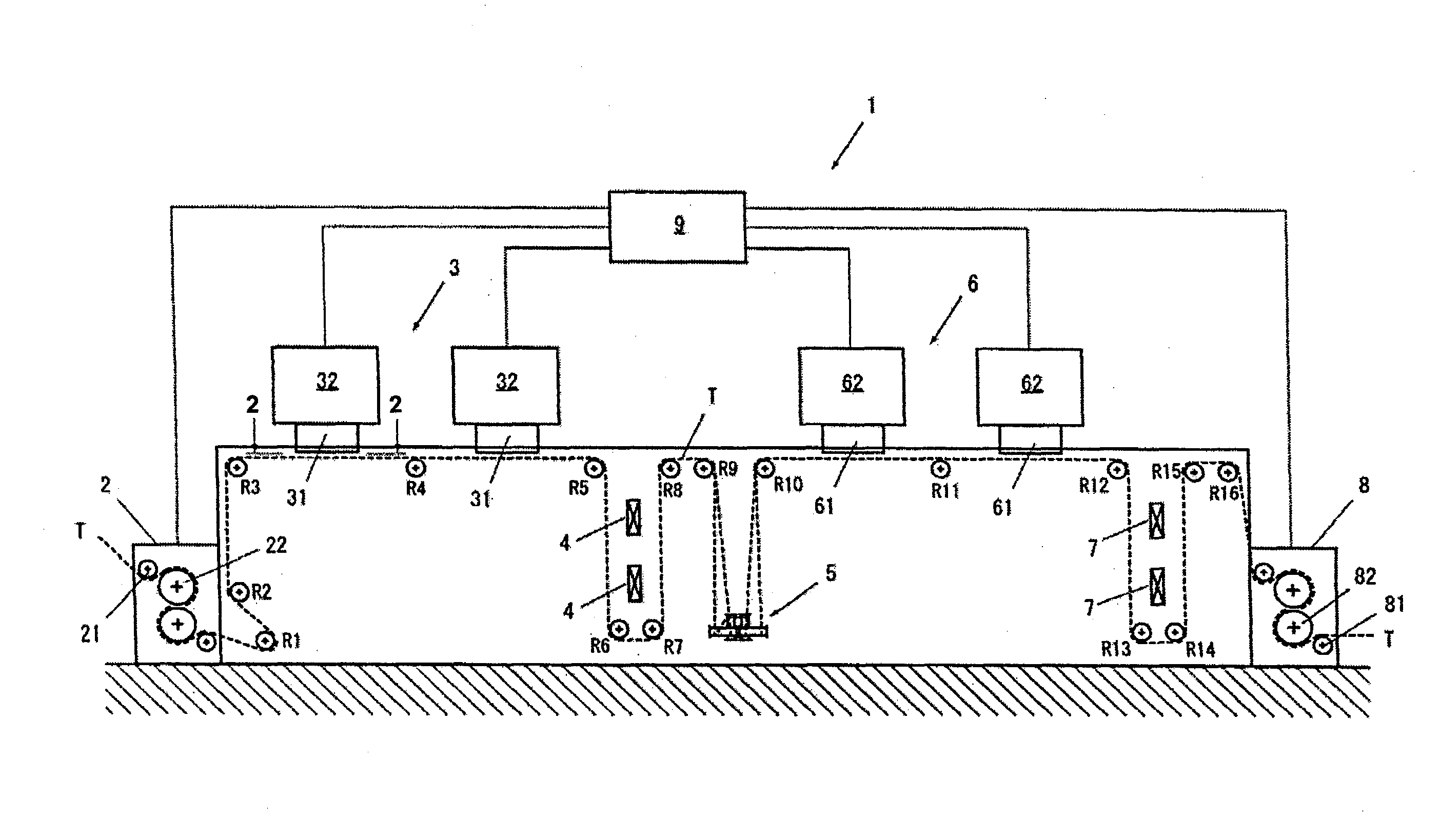
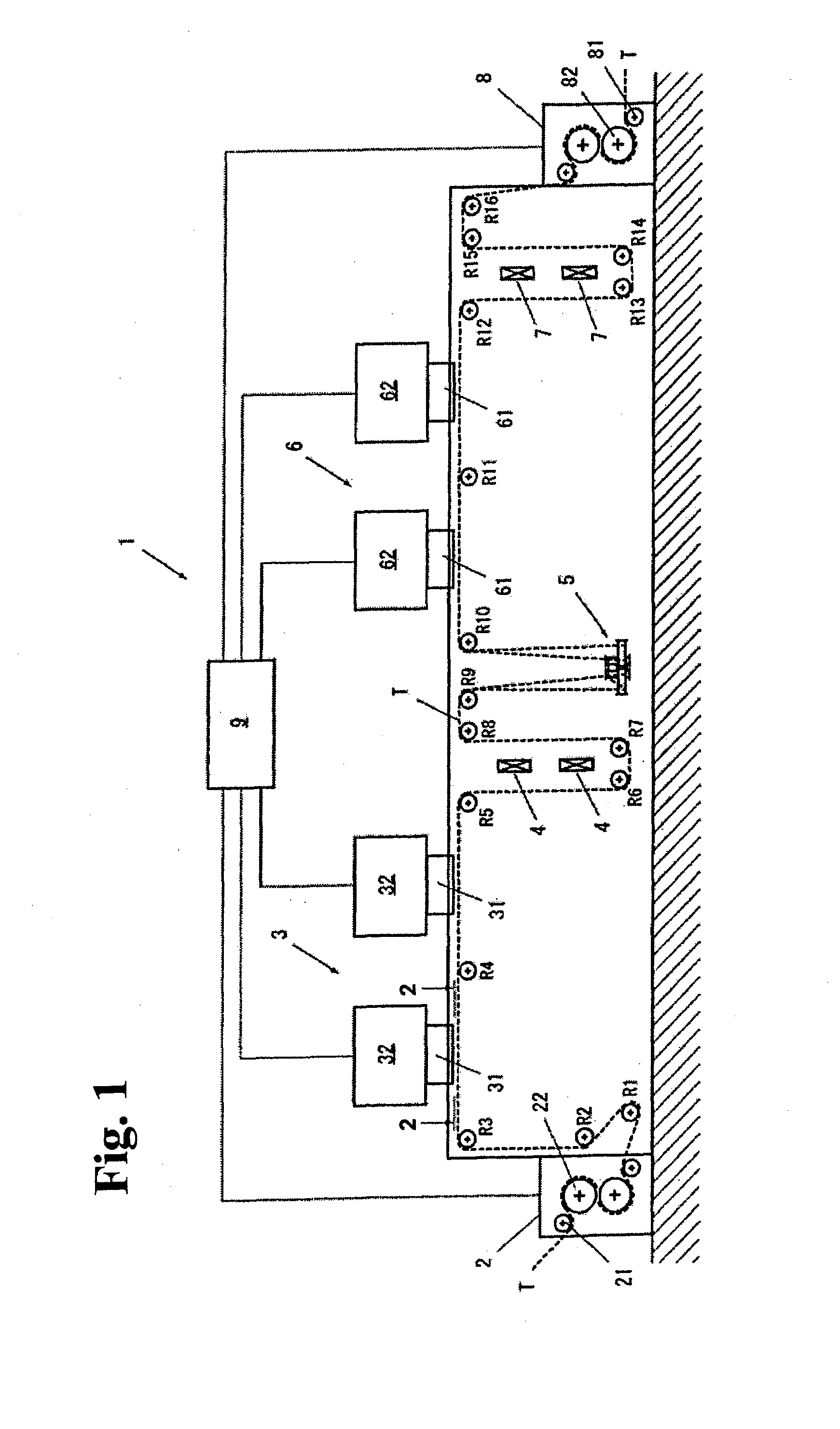
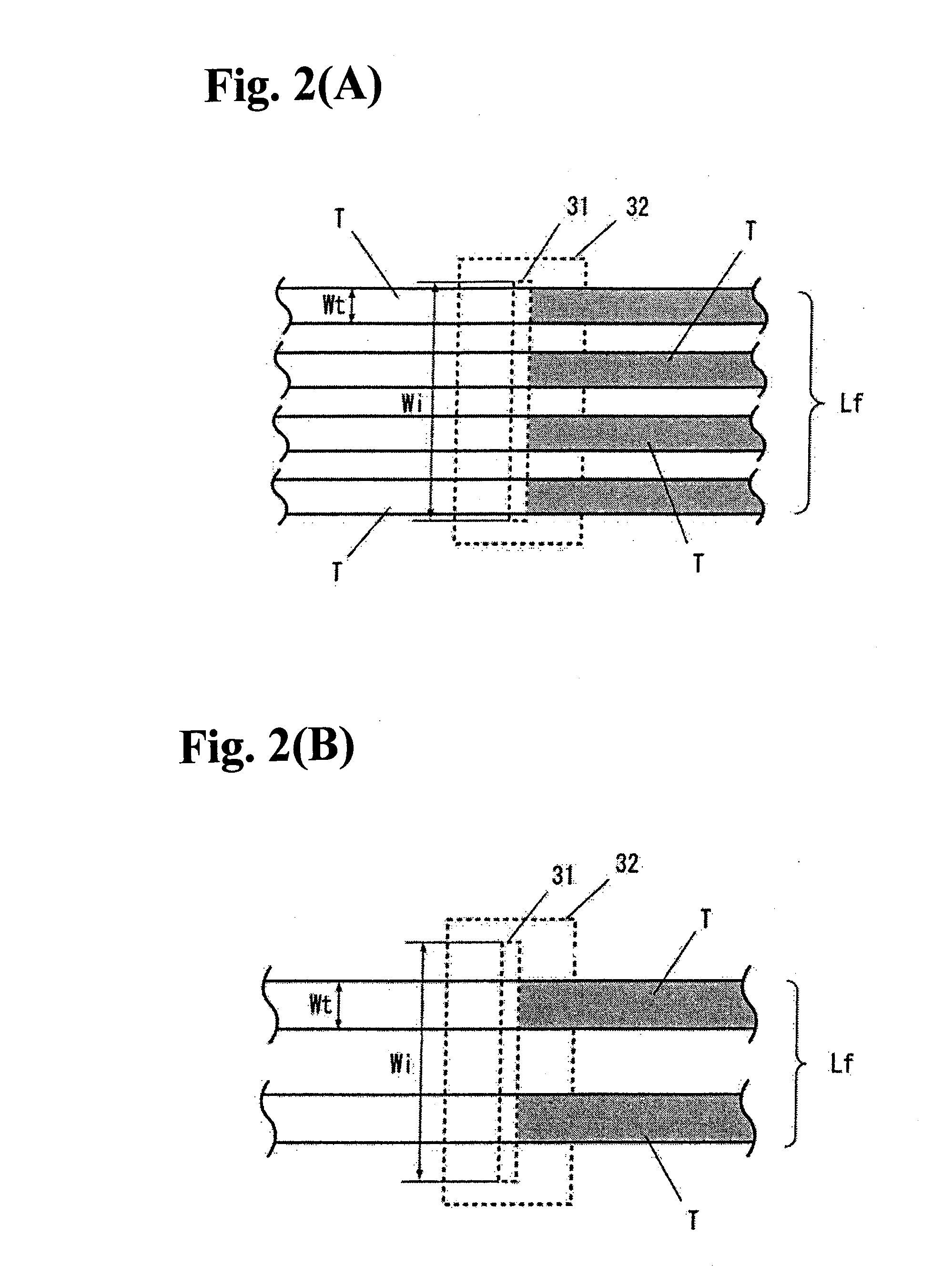
[0027]Embodiments of the present invention will be described below with reference to FIGS. 1 to 8. FIG. 1 is a configuration diagram showing an inkjet dyeing apparatus according to the present invention. FIGS. 2(A), 2(B) are views taken along line 2-2 of FIG. 1, wherein FIG. 2(a) shows the case where four textiles are subjected to printing, while FIG. 2(B) shows the case where two textiles are subjected to printing. Shadow areas in FIGS. 2(A), 2(B) show the printed state of a textile.

[0028]An inkjet dyeing apparatus 1 as shown in FIG. 1 is an inkjet dyeing apparatus that dyes a belt-like textile T by ejecting ink, which includes a feeding section 2 for transporting the textile T to a front surface printing line Lf, a front surface printing section 3, disposed on the front surface printing line Lf, which dyes the front surface of the textile T by ejecting ink, a front surface drying section 4 for drying the front surface of the textile T, an inverting section 5 that inverts the texti...

second embodiment

[0043]The inkjet dyeing apparatus 1 has the front surface drying section 4 and the inverting section 5 disposed below the front surface printing section 3 and has the rear surface drying section 7 disposed below the rear surface printing section 6. As just described, disposing the drying sections 4, 7 and the inverting section 5 below the printing sections 3, 6 can reduce dead spaces inside the inkjet dyeing apparatus, thereby allowing downsizing of the apparatus. In particular, the overall length L of the inkjet dyeing apparatus 1 can be reduced.

[0044]According to the inkjet dyeing apparatus 1 as described above, the textile T can be transported to the inkjet dyeing apparatus 1 from the feeding section 2, transported to the front surface printing section 3 through the transporting rollers R1 to R4, transported back to below the upstream front surface printing section 3 through transporting rollers R5 to R7, transported to the front surface drying section 4 through the transporting...

third embodiment

[0045]The inkjet dyeing apparatus 1 as shown in FIG. 5, includes a feeding section 2 for feeding a textile T to a front surface printing line Lf, a printing section 10, disposed on the front surface printing line Lf, which dyes the textile by ejecting onto the front surface of the textile T, a front surface drying section 4 for drying the front surface of the textile T, an inverting section 5 that inverts and feeds the textile T to the rear surface printing line Lr, a printing section 10, disposed on the rear surface printing line Lr, which dyes the textile by ejecting ink onto the rear surface of the textile T, a rear surface drying section 7 for drying the rear surface of the textile T, a transporting section 8 for transporting out the textile T to the next step, and a control unit 9 for controlling the ejecting of the ink. The printing section 10 has a structure similar to that of the front surface printing section 3 or the rear surface printing section 6, including an inkjet he...


PUM

PropertyMeasurementUnit
widthaaaaaaaaaa
widthaaaaaaaaaa
widthaaaaaaaaaa

Abstract

An inkjet dyeing apparatus for dyeing a belt-shape textile includes a feeding section for feeding the textile, a front surface printing section for dyeing a front surface of the textile by ink ejected thereon, a front surface drying section for drying the front surface of the textile, an inverting section for inverting and feeding the textile to a rear surface printing line, a rear surface printing section for dyeing the rear surface of the textile by ink ejected thereon, and a rear surface drying section for drying the rear surface of the textile. A transporting section is provided to transport the textile for further processing. A control unit controls ink ejection at the front and rear surface printing sections.

Description

BACKGROUND OF THE INVENTION AND RELATED-ART STATEMENT[0001]The present invention relates to an inkjet dyeing method and apparatus. More specifically, it relates to an inkjet dyeing method and apparatus suitable for continuous printing on a belt-like textile such as a seat belt webbing.[0002]As a dyeing method for seat belt webbing, a method disclosed in, for example, Japanese Patent No. 3240674: Patent Document 1 is known. According to the method disclosed in Patent Document 1, the seat belt webbing is subjected to a certain amount of tension with a first tensioner and a second tensioner while it is immersed in a dye solution in a dye padding process for a dye attachment and dried in a hot-air oven for dye developing and fixing.[0003]Also, a method disclosed in, for example, Japanese Unexamined Patent Application Publication No. 5-318721: Patent Document 2 is known as a method for recording (printing) of a cloth or wallpaper. According to the method disclosed in Patent Document 2, a...

Claims


Application Information

Patent Timeline
Patent Type & Authority Applications(United States)
IPC IPC(8): D06P5/15D06F33/00
CPCB41J3/4078B41J3/543B41J15/165B41J11/002B41J3/60B41J11/00216
Inventor FUKUI, AKIRA
Owner JOYSON SAFETY SYST JAPAN GK
Why Eureka
Try Eureka