System and method for controlling exhaust stream temperature

a technology of exhaust stream and control system, applied in adaptive control, process and machine control, instruments, etc., can solve problems such as system failure to provide acceptable control performance, and achieve the effect of reducing errors

Active Publication Date: 2010-03-04
CORNING INC
View PDF15 Cites 37 Cited by
  • Summary
  • Abstract
  • Description
  • Claims
  • Application Information

AI Technical Summary

Benefits of technology

[0007]In accordance with a further aspect of the invention, provided is a regeneration control system for an engine exhaust system. The regeneration control system includes an oxidation catalyst, and a particulate filter including an outlet. A fuel injector injects fuel into an exhaust stream at a location upstream from the outlet of the particulate filter. The exhaust stream flows through the particulate filter. A processor controls an operation of the fuel injector based on an adaptive control model that adaptively models a portion of the exhaust system. The processor is programmed to calculate a fuel injection flow rate based on the adaptive control model, control the operation of the fuel injector to control an exhaust stream temperature at a point along the exhaust system, determine an error in the adaptive control model based on a monitored condition of the engine exhaust system, and change the adaptive control model to reduce the error.

Problems solved by technology

However, such systems may not provide acceptable control performance under various dynamic conditions, such as when engine speed and / or torque are dynamically changing.

Method used


Image

  • System and method for controlling exhaust stream temperature
  • System and method for controlling exhaust stream temperature
  • System and method for controlling exhaust stream temperature

Examples


Embodiment Construction

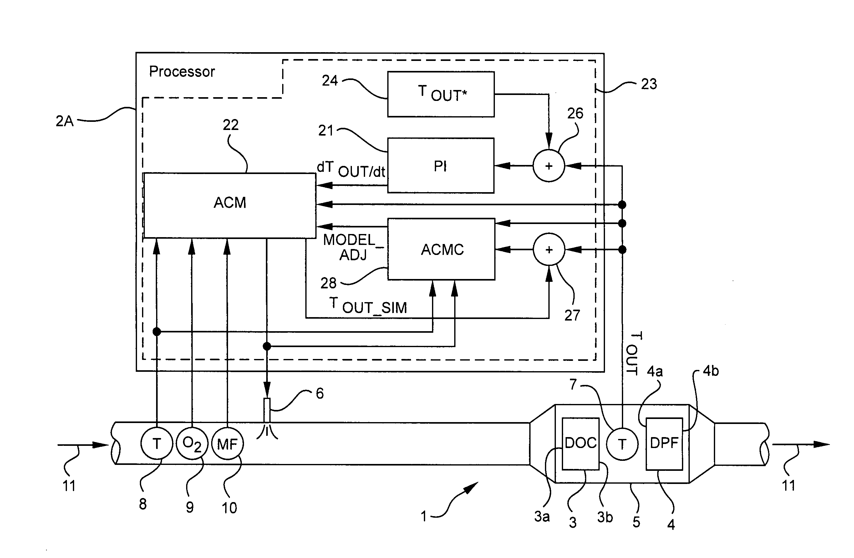
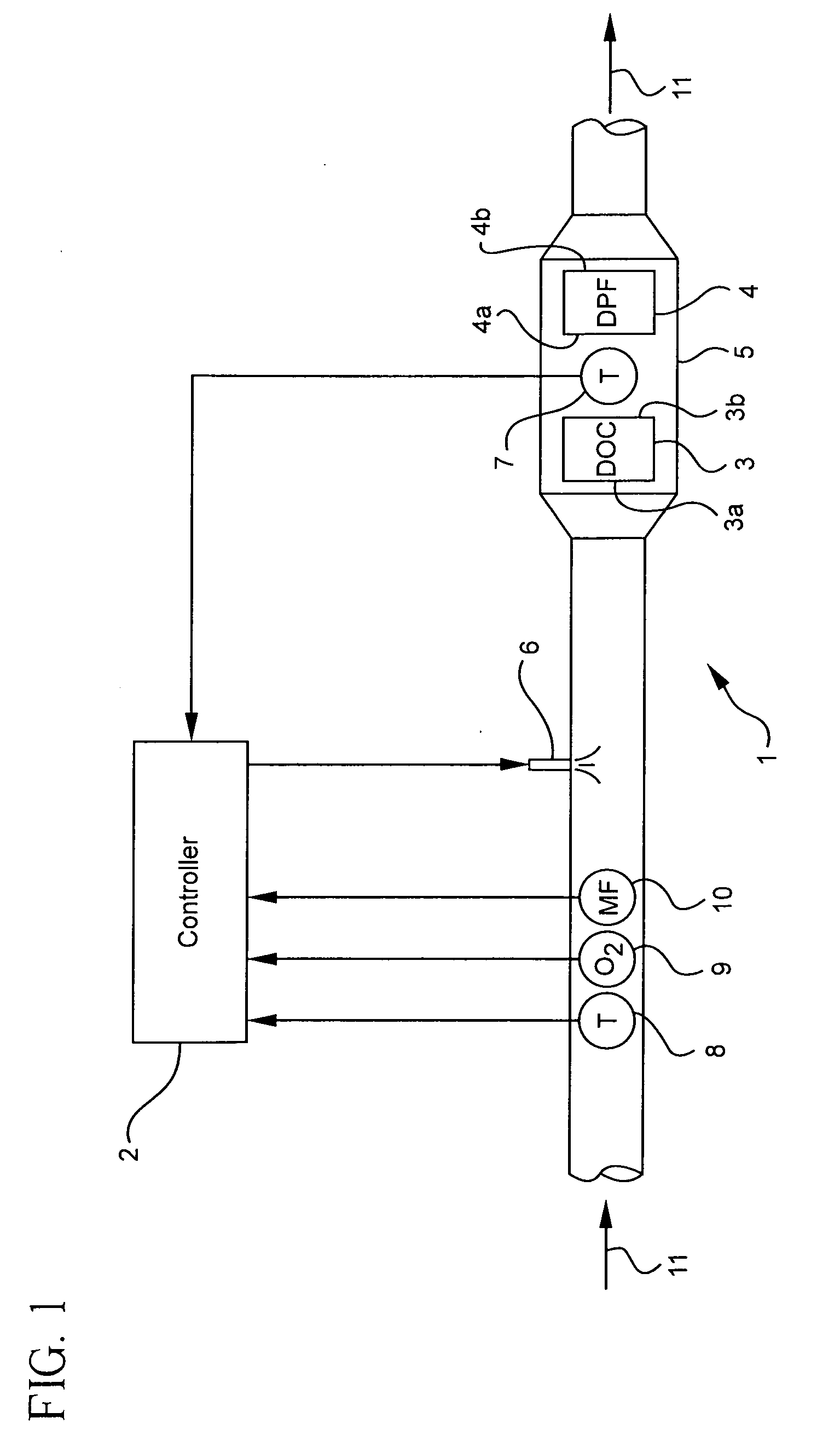
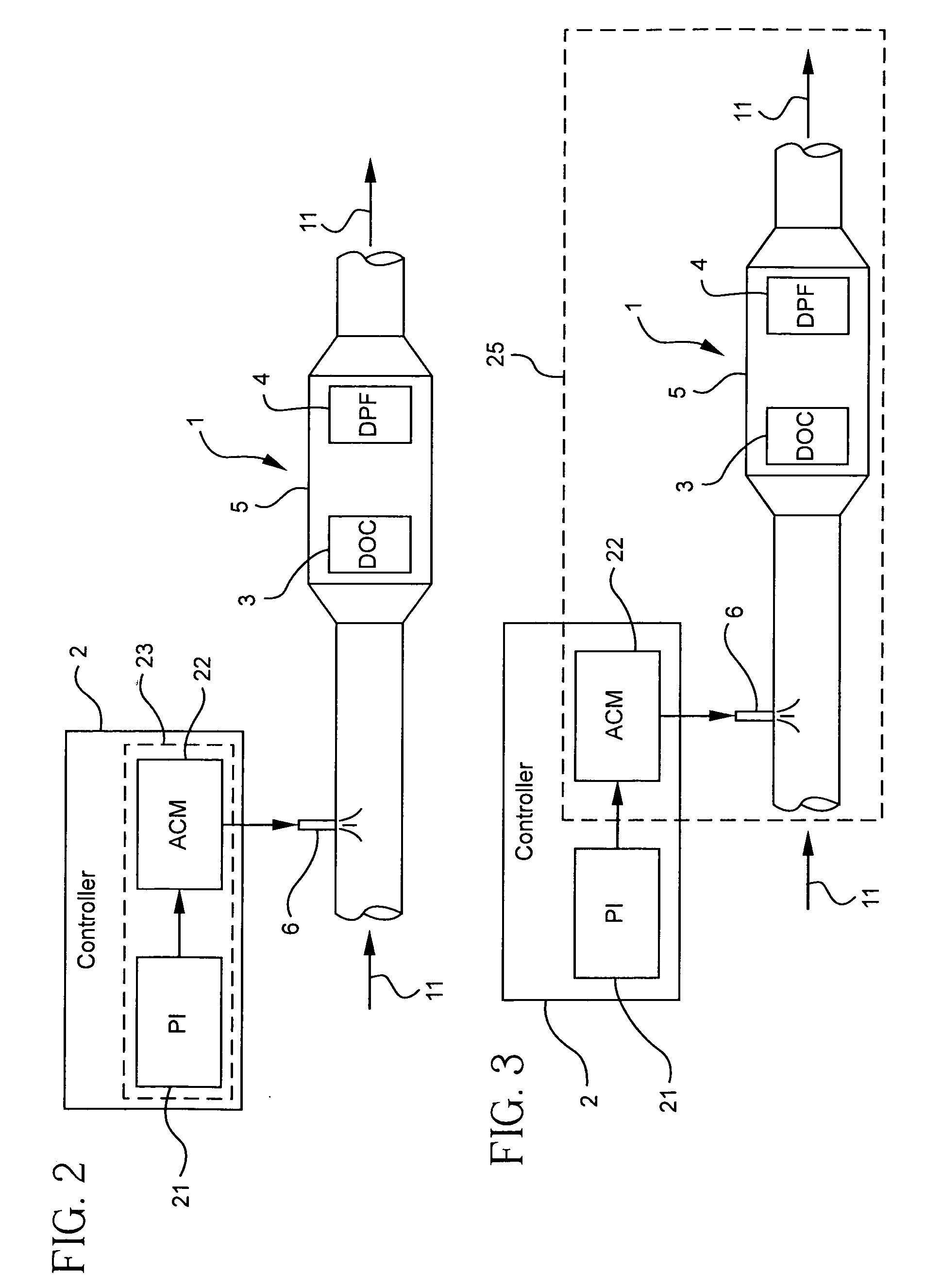
[0013]Features and aspects of the present invention will now be described more fully hereinafter with reference to the accompanying drawings in which example embodiments are shown. Whenever possible, the same reference numerals are used throughout the drawings to refer to the same or like parts. However, this invention may be embodied in many different forms and should not be construed as limited to the embodiments set forth herein. These example embodiments are provided so that this disclosure will be both thorough and complete, and will fully convey the scope of the invention to those skilled in the art.

[0014]Control methodologies are included in the following description. The control methodologies may reference specific portions, components, inputs or outputs of a controlled system, for purposes of explaining the control methodologies. It may be evident, however, that the control methodologies can be effectively applied to other portions, components, inputs or outputs of the cont...


PUM


Abstract

Systems and methods are provided for controlling an exhaust stream temperature at a point along an exhaust system. The exhaust system can include an oxidation catalyst, a particulate filter having an outlet, and a fuel injector for injecting fuel into an exhaust stream at a location upstream from the outlet. An adaptive control can be provided to model a portion of the exhaust system. A fuel injection flow rate at which fuel is injected into the exhaust stream by the fuel injector can be calculated based on the adaptive control model. An operation of the fuel injector can be controlled based on the calculated fuel injection flow rate, to control the exhaust stream temperature at point along the exhaust system. A condition of the exhaust stream can also monitored and an error in the adaptive control model can be determined based on the monitored condition. The adaptive control model can also be changed to reduce the error.

Description

BACKGROUND[0001]1. Field[0002]The present disclosure relates to engine exhaust systems. More particularly, the present disclosure relates to systems and methods for controlling an exhaust stream temperature in an engine exhaust system and controlling the regeneration of a particulate filter.[0003]2. Description of Related Art[0004]It is known to control the temperature within a particulate filter of a diesel engine exhaust system to regenerate the filter at a desired temperature. Known control systems for controlling the temperature may operate adequately under steady-state conditions. However, such systems may not provide acceptable control performance under various dynamic conditions, such as when engine speed and / or torque are dynamically changing.SUMMARY[0005]In accordance with one aspect of the invention, provided is a method of controlling an exhaust stream temperature at a point along an exhaust system. The exhaust system includes an oxidation catalyst, a particulate filter i...

Claims


Application Information

Patent Timeline
Patent Type & Authority Applications(United States)
IPC IPC(8): F01N3/025
CPCF01N3/0253F01N13/0097F01N9/002F01N9/005F01N2560/025F01N2560/06F01N2560/07F01N2560/14F01N2610/146F01N2900/0402F01N2900/0404F01N2900/0422F01N2900/1631Y02T10/47F01N3/035Y02T10/40
Inventor HE, SUHAOHEIBEL, ACHIM KARL-ERICHQIU, WENBIN
Owner CORNING INC
Why Eureka
Try Eureka