
Fan apparency arrangement for an appliance

a technology of apparency arrangement and fan, which is applied in the direction of gaseous heating fuel, domestic stoves or ranges, heating types, etc., can solve the problems of requiring extensive testing, preventing the selected heating operation of the oven from proceeding, and the reaction time of the thermal switch is relatively slow

Active Publication Date: 2010-03-04
HAIER US APPLIANCE SOLUTIONS INC
View PDF47 Cites 10 Cited by
  • Summary
  • Abstract
  • Description
  • Claims
  • Application Information

AI Technical Summary

Benefits of technology

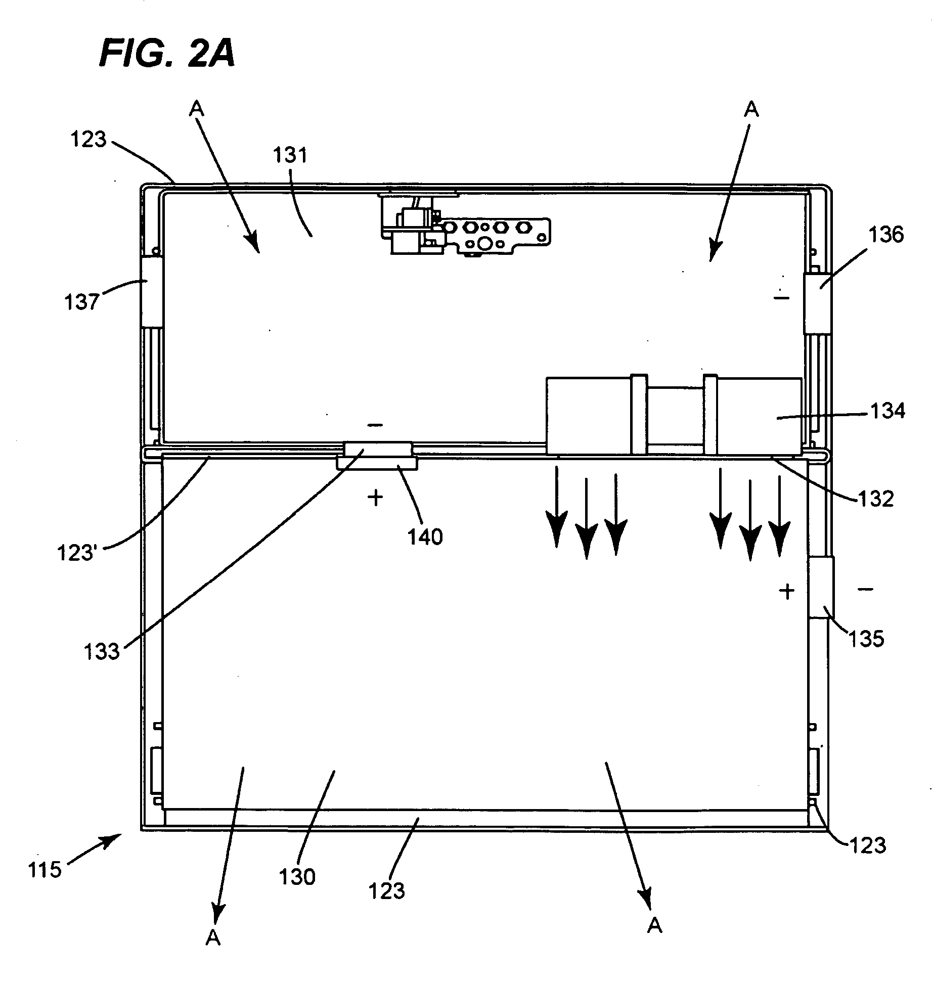
[0009]Yet another aspect of the present invention relates to an appliance that includes a chamber having a first port and a second port, an air blower disposed in the chamber, and a pressure sensitive device disposed adjacent to the second port. The pressure sensitive device includes a switch for signaling the activation of the air blower, and a sail member pivotably supported by the chamber. The sail member is movable between a first position where the sail member does not turn on the switch and a second position where the sail member turns on the switch to signal the activation of the air blower. When activated, the air blower moves air out of the chamber through the first port to create a pressure difference between an inside and an outside of the chamber. The pressure difference causes the sail member to move from the first position to the second position.

Problems solved by technology

On the other hand, if the fan is stalled or not working properly, the FAD prevents the selected heating operation for the oven from proceeding.
However, the thermal switch has a relatively slow reaction time.
Moreover, the thermal switch requires extensive testing to prove that it will work as intended in all working conditions of the oven.
However, since the sail is disposed downstream and in the flow-path of the fan, it negatively affects the airflow passing through the fan.
Additionally, the sail becomes an undesirable dynamic load for the fan.

Method used


Image

  • Fan apparency arrangement for an appliance
  • Fan apparency arrangement for an appliance
  • Fan apparency arrangement for an appliance

Examples


Embodiment Construction

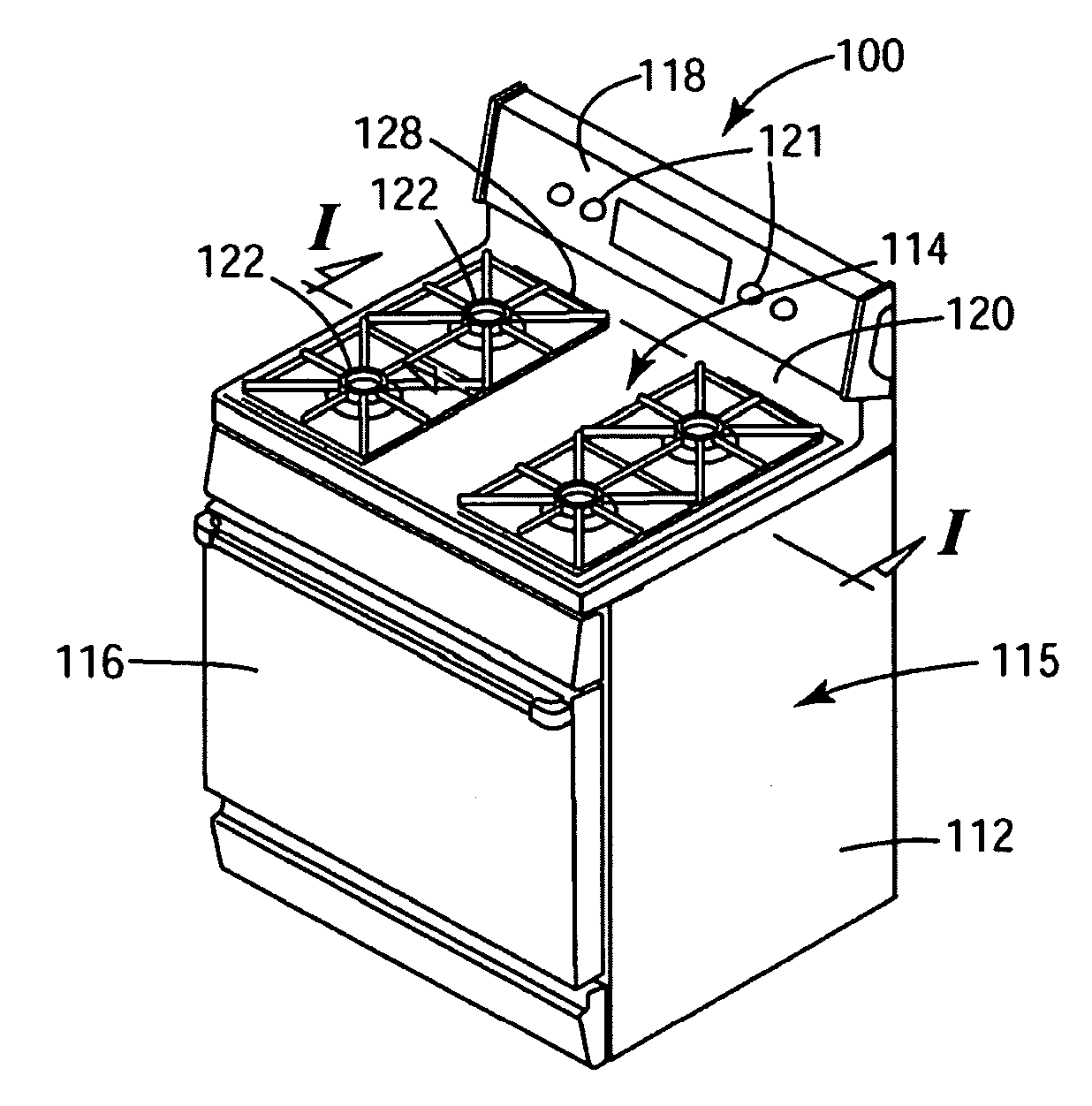
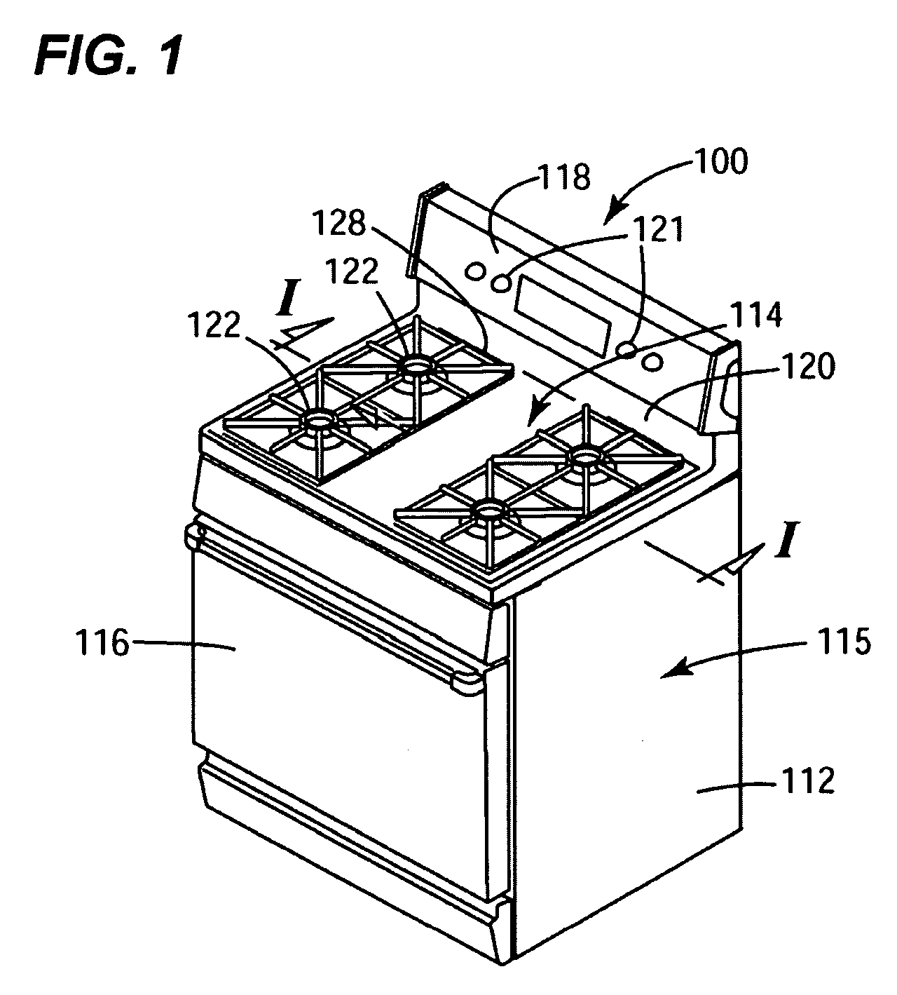
[0019]An exemplary appliance incorporating a fan apparency arrangement in accordance with a preferred embodiment of the present invention is generally designated by reference numeral 100 in FIG. 1. By way of non-limiting example, the appliance 100 is shown as a freestanding cooking range in FIG. 1. However, the preferred embodiments of the present invention can also be used in other types of appliances such as ovens, dryers, etc.

[0020]The cooking range 100 includes an outer body or housing 112 that has a generally rectangular shaped cook top 114. An oven 115, not shown in detail, is positioned below the cook top 114 and has a front-opening access door 116 for closing the oven cavity. Preferably, an integral backsplash 118 extends upward from a rear edge 120 of the cook top 114 and contains various controls 121 for selectively operating heating elements such as gas burners 122 on the cook top 114 and heating elements (not shown) in the oven 115.

[0021]As clearly shown in FIGS. 2A-2C, ...


PUM


Abstract

A fan apparency arrangement for an appliance is disclosed. The appliance has a chamber with a first port and a second port. The arrangement includes a fan for moving air in or out of the chamber, and a sail switch disposed adjacent to the second port. When activated, the fan moves air in or out of the chamber through the first port to create a pressure difference between an inside and an outside of the chamber. The pressure difference causes the sail switch to change position and signal that the fan is activated. An appliance incorporating such a fan apparency arrangement is also disclosed.

Description

BACKGROUND OF THE INVENTION[0001]The present invention relates generally to a fan apparency arrangement. More particularly, the present invention relates to a fan apparency arrangement for an appliance and an appliance incorporating such a fan apparency arrangement.[0002]Appliances such as cooking ranges and wall ovens are widely used. A cooking range typically includes an oven with a front-opening access door, and at least one heating element for heating up the inside of the oven cavity. Wall ovens have a similar configuration. As is known in the art, when energized, the heating element can heat up the inside of the oven cavity to a relatively high temperature. Also as is known in the art, such cooking appliance often has a fan which is used to draw cooling air into the interior of the appliance to cool a structural component of the appliance, such as the front-opening access door, or a heat sensitive component such as an electronic control. If an appliance employs a fan for coolin...

Claims


Application Information

Patent Timeline
Patent Type & Authority Applications(United States)
IPC IPC(8): F28D15/00F24C15/00
CPCF24C15/006F24C15/2007F24C5/16A21B3/04A21B3/02A21B1/40
Inventor ARMSTRONG, JAMESMAST, CHRISTOPHERWATKINS, DEREK LEEBROWN, JUSTIN T.
Owner HAIER US APPLIANCE SOLUTIONS INC
Learn More